
Storage cage convenient to use

A technology for storage cages and side panels, which is applied in the field of storage cages, can solve the problems of large space occupation, easy slipping, loss of enterprises, etc., and achieve the effect of reducing occupied space, fixed capacity, and saving space

Inactive Publication Date: 2019-02-26
徐州鹏亮物流有限公司
View PDF0 Cites 0 Cited by
  • Summary
  • Abstract
  • Description
  • Claims
  • Application Information

AI Technical Summary

Problems solved by technology

[0002] Storage cage, also known as storage cage, is widely used in machinery, automobiles, home appliances, light industry, electronics and other industries to store or transport turnover machines, parts or other bulk objects. It is one of the important logistics containers in warehousing and transportation. It has the advantages of fixed capacity, neat stacking, clear storage, and easy inventory inventory. It can also improve the effective utilization of storage space. It is an important type of logistics container in warehousing and transportation, which effectively reduces the labor consumption and packaging costs of enterprises. The storage cage is made of mesh, with simple structure, small bearing capacity, poor stability, easy to deform when stacked, and even collapse, which will not only damage the goods, but also endanger the health of the staff, and bring unnecessary damage to the enterprise. In addition, the existing storage cages do not have the folding function, and they take up a lot of space during stacking or transportation of empty cages, which increases transportation costs. A small number of storage cages with folding functions are warped on the storage board after folding. In this case Stacking the storage cages together is easy to slip and accidentally injure the staff

Method used


Image

  • Storage cage convenient to use
  • Storage cage convenient to use
  • Storage cage convenient to use

Examples


Embodiment Construction

[0016] The present invention will be described in further detail below in conjunction with the accompanying drawings.

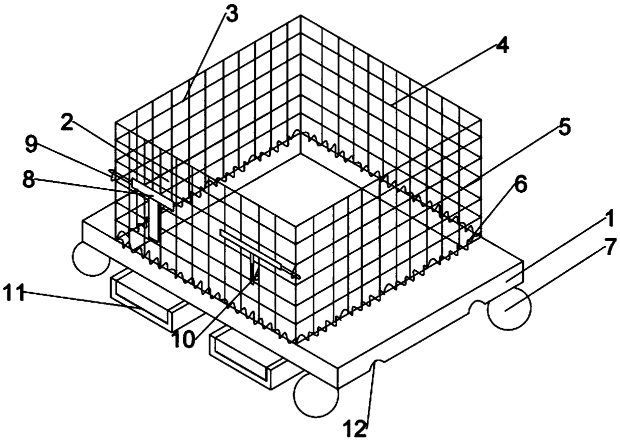
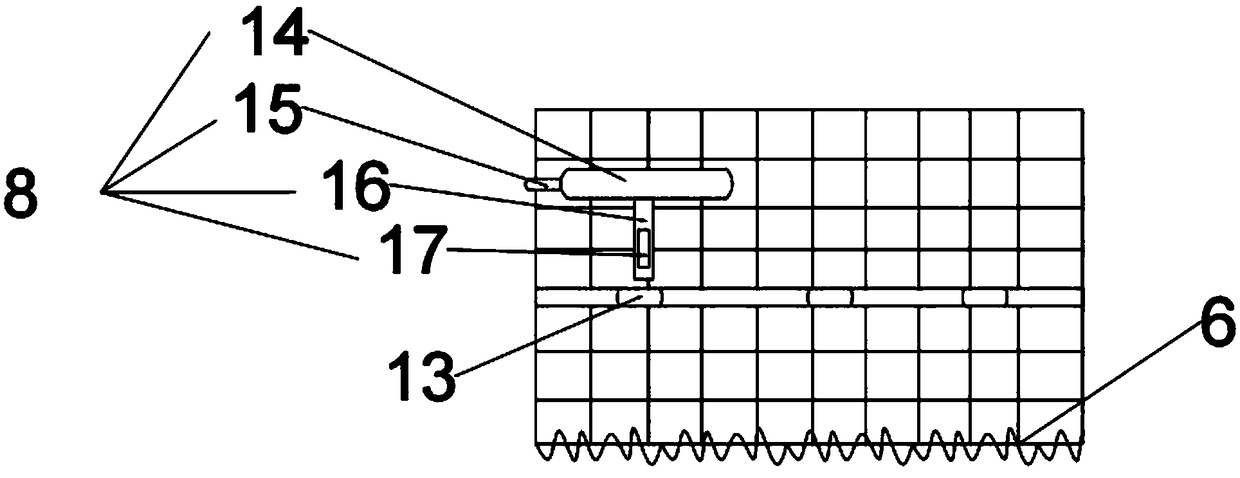
[0017] In conjunction with the accompanying drawings, a storage cage that is easy to use includes a base 1, a front plate 2 connected to the base 1, a side plate 3, a rear plate 4 and a side plate 2 5, the base 1 is rectangular, and the base 1 center is provided with central groove 18, and described front plate 2, side plate one 3, rear plate 4 and side plate two 5 are respectively connected with the four sides of central groove 18, and described front plate 2, side plate one 3, rear plate 4 and side plate two 5 and the four sides of central groove 18 are provided with spring steel wire 6, and described front plate 2, side plate one 3, rear plate 4 and side plate two 5 are hinged with the four sides of central groove 18 by spring steel wire 6 , the front plate 2 is movably connected with the side plate 1 3 and the side plate 2 5 through the bolt 8, and the re...


PUM


Abstract

The invention relates to a storage cage convenient to use. The storage cage comprises a base, a front plate connected with the base, a first side plate, a back plate and a second side plate, the baseis rectangular, and a center groove is formed in the center of the base; the front plate, the first side plate, the back plate and the second side plate are respectively connected with the four sidesof the center groove, spring steel wires are arranged between the front plate, the first side plate, the back plate and the second side plate and the four sides of the center groove, and the front plate is movably connected with the first side plate and the second side plate through plugs; the back plate is movably connected with the first side plate and the second side plate through plugs, the opening and closing states of the plugs control the connecting state among the front plate, the first side plate, the back plate and the second side plate, and the locking state of the plugs makes the front plate, the first side plate, the back plate and the second side plate connected and erected to be in a storage state. Compared with the prior art, the storage cage has the advantage that empty cages can be conveniently piled, and the storage cage is convenient to use.

Description

technical field [0001] The invention relates to the technical field of storage, in particular to an easy-to-use storage cage. Background technique [0002] Storage cage, also known as storage cage, is widely used in machinery, automobiles, home appliances, light industry, electronics and other industries to store or transport turnover machines, parts or other bulk objects. It is one of the important logistics containers in warehousing and transportation. It has the advantages of fixed capacity, neat stacking, clear storage, and easy inventory inventory. It can also improve the effective utilization of storage space. It is an important type of logistics container in warehousing and transportation, which effectively reduces the labor consumption and packaging costs of enterprises. The storage cage is made of mesh, with simple structure, small bearing capacity, poor stability, easy to deform when stacked, and even collapse, which will not only damage the goods, but also endange...

Claims


Application Information

Patent Timeline
Patent Type & Authority Applications(China)
IPC IPC(8): B65D6/16B65D19/38B65D19/42B65D21/02
CPCB65D7/24B65D9/12B65D11/18B65D19/38B65D19/42B65D21/02
Inventor 石纹景张秋
Owner 徐州鹏亮物流有限公司
Learn More