Al technical title is built by PatSnap Al team. It summarizes the technical point description of the patent document.
A hydraulic jack, electric technology, applied in the direction of circuits, fuel cells, electrical components, etc., can solve the problems of physical exertion, hidden safety hazards of operators, etc., and achieve the effect of low cost, good safety, and improved convenience and safety
Inactive Publication Date: 2019-02-26
GUANGDONG HYDROGEN ENERGY SCI & TECH
View PDF4 Cites 2 Cited by
Summary
Abstract
Description
Claims
Application Information
AI Technical Summary
This helps you quickly interpret patents by identifying the three key elements:
Problems solved by technology
Method used
Benefits of technology
Problems solved by technology
Existing jack structures are physically demanding and pose a safety hazard to operators
Method used
Image
Click on the blue label to locate the original text in one second.
Reading with bidirectional positioning of images and text.
Examples
Embodiment 1
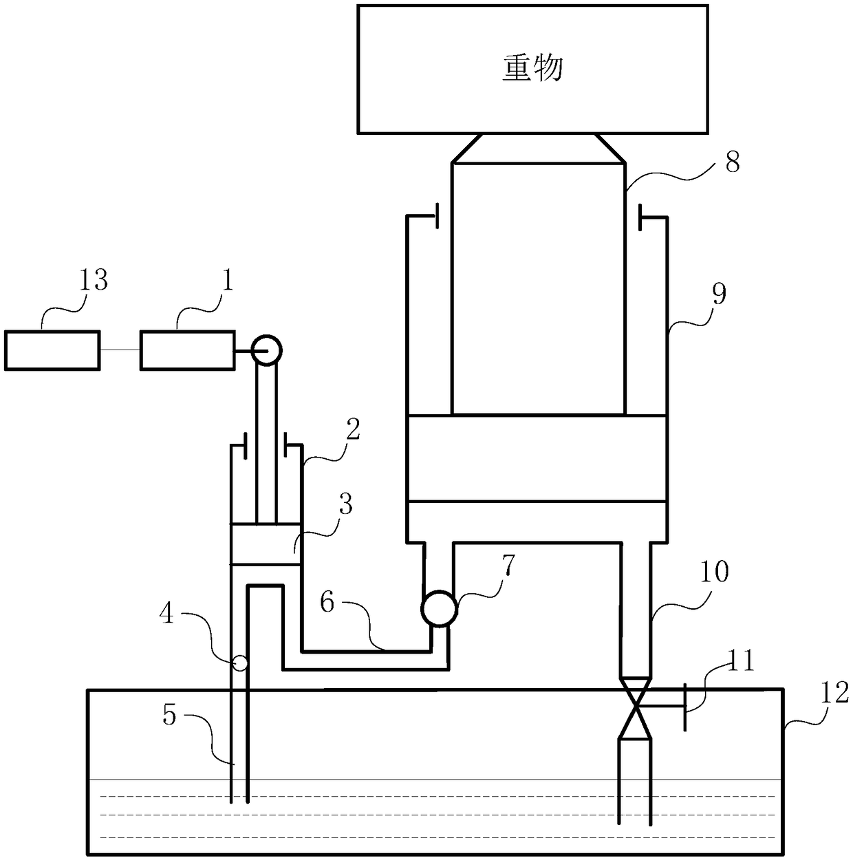
[0033] see figure 1 , figure 2 , the present invention discloses an electro-hydraulic jack, the electro-hydraulic jack includes: a fuel tank 12, a large oil cylinder 9, a large piston 8, a stop valve 11, a first pipeline 5, a second pipeline 6, and a third pipeline 10 , a hydraulic drive motor 1, a small oil cylinder 2, a small piston 3, a first one-way solenoid valve 4, a second one-way solenoid valve 7, a main control circuit 14, and a power supply module 13.
[0034] The large oil cylinder 9 and the large piston 8 form a lifting hydraulic cylinder, and the hydraulic drive motor 1, small oil cylinder 2, small piston 3, first one-way solenoid valve 4, and second one-way solenoid valve 7 form an electric hydraulic pump.
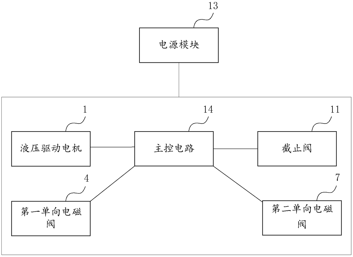
[0035] The main control circuit 14 is respectively connected to the hydraulic drive motor 1 , the first one-way solenoid valve 4 , the second one-way solenoid valve 7 , the shut-off valve 11 and the power supply module 13 to control their operation.
[003...
Embodiment 2
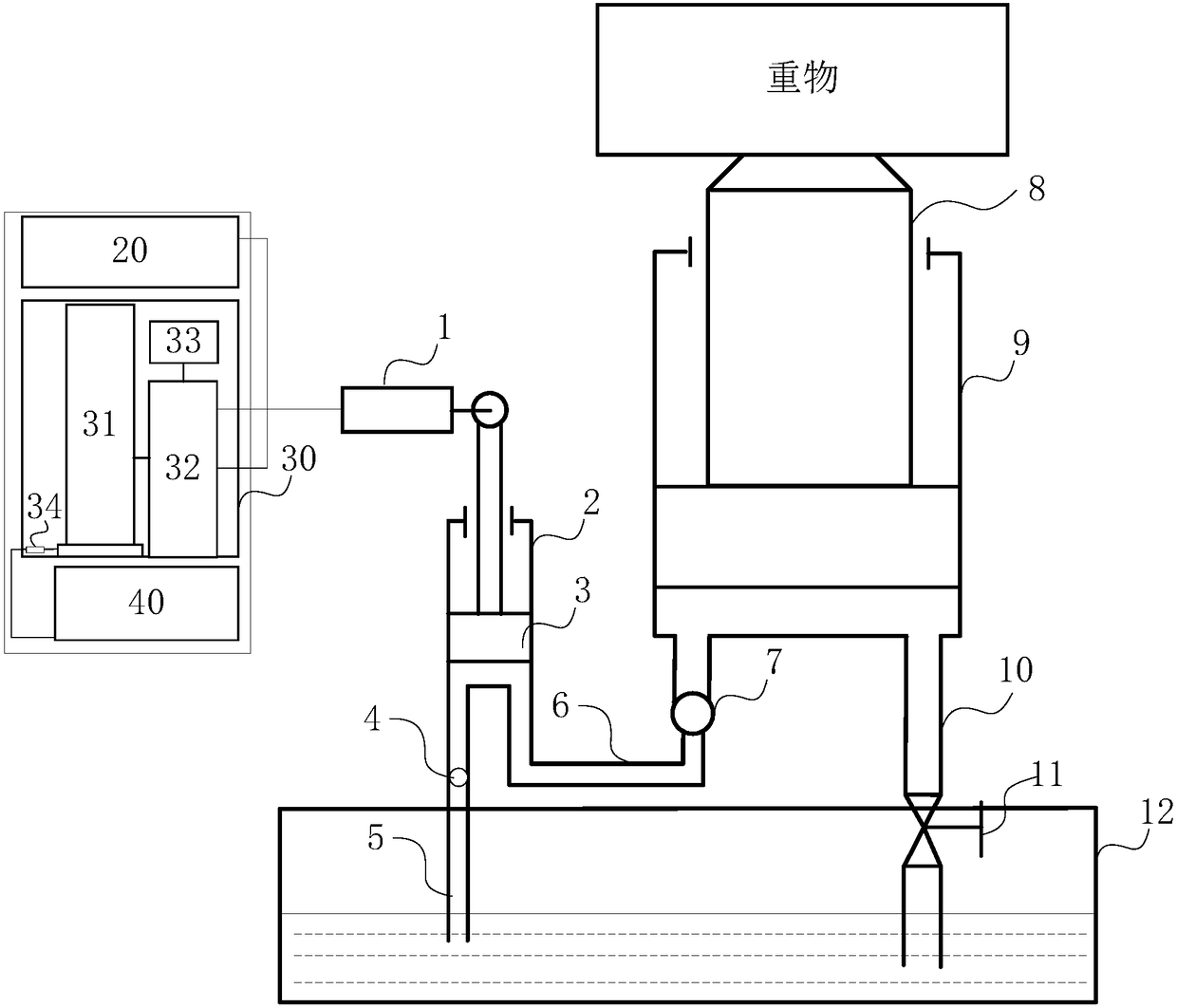
[0045] The difference between this embodiment and Embodiment 1 is that in this embodiment, the power module includes a lithium battery.
Embodiment 3
[0047] The difference between this embodiment and Embodiment 1 is that in this embodiment, the power module includes a hydrogen storage tank and a hydrogen fuel cell. Circuits, travel drive motors, steering drive motors, and height adjustment mechanisms.
PUM
Abstract
The invention discloses an electric hydraulic jack. The electric hydraulic jack comprises an oil tank, a large oil cylinder, a large piston, a shut-off valve, a first pipeline, a second pipeline, a third pipeline, a hydraulic driving motor, a small oil cylinder, a small piston, a first one-way electromagnetic valve, a second one-way electromagnetic valve, a main control circuit and a power supplymodule; the large oil cylinder and the large piston constitute a lifting hydraulic cylinder, and the hydraulic driving motor, the small oil cylinder, the small piston, the first one-way electromagnetic valve and the second one-way electromagnetic valve constitute an electric hydraulic pump; the hydraulic driving motor is connected to the small piston located in the small oil cylinder and can drivethe small piston to move in the small oil cylinder; the small oil cylinder is connected to the oil tank through the first pipeline, and a first one-way valve is arranged in the first pipeline; the small oil cylinder is connected to the large oil cylinder through the second pipeline, and a second one-way valve is disposed in the second pipeline; the large oil cylinder is connected to the oil tankthrough the third pipeline which is provided with the shut-off valve. The provided electric hydraulic jack can achieve electric work and improve the use convenience and safety.
Description
technical field [0001] The invention belongs to the technical field of jacks, and relates to a jack, in particular to an electrohydraulic jack. Background technique [0002] The jack is the simplest lifting equipment with a lifting height of less than 1m. It uses a rigid top lifting piece as a working device, and is a light and small lifting equipment that lifts heavy objects in the stroke through the top bracket or bottom claw. Divided into two kinds of mechanical type and hydraulic type, the jack is mainly used in factories, mines, transportation and other departments as vehicle repair and other lifting, support and other work. Its structure is light and strong, flexible and reliable, and can be carried and operated by one person. [0003] Existing jacks usually need to be manually operated, and the operator needs to be close to the gradually lifted heavy object, and at the same time needs to rotate the rotating rod or press the cross bar to make the jack gradually lift t...
Claims
Application Information
Patent Timeline
Application Date:The date an application was filed.
Publication Date:The date a patent or application was officially published.
First Publication Date:The earliest publication date of a patent with the same application number.
Issue Date:Publication date of the patent grant document.
PCT Entry Date:The Entry date of PCT National Phase.
Estimated Expiry Date:The statutory expiry date of a patent right according to the Patent Law, and it is the longest term of protection that the patent right can achieve without the termination of the patent right due to other reasons(Term extension factor has been taken into account ).
Invalid Date:Actual expiry date is based on effective date or publication date of legal transaction data of invalid patent.