
Auxiliary yarn guiding arm structure of yarn feeding wheel of dyeing machine

A technology of yarn feeder and yarn guide arm

Inactive Publication Date: 2019-02-26
DONGGUAN JINFU HARDWARE MACHINERY +1
View PDF6 Cites 0 Cited by
  • Summary
  • Abstract
  • Description
  • Claims
  • Application Information

AI Technical Summary

Problems solved by technology

However, because the yarn contains yarn oil, the yarn oil will adhere to the apron, which will cause the apron to age over time, so that when the yarn feeding wheel stops eating yarn, the yarn will still stick to the surface of the apron. As a result, the yarn guide arm cannot be bounced off in time, so that the yarn is drawn into the yarn feeding wheel, and the purpose of yarn change cannot be successfully completed
Furthermore, if the opening angle of the yarn guide arm is not large enough, the yarn will stick to the surface of the apron excessively, which will also increase the friction area and cause damage to the yarn.
[0003] In addition, although the elastic force of the yarn guide arm can be increased to make the yarn quickly break away from the friction surface of the yarn feeding wheel, this will inevitably cause the yarn to bear excessive tension, which will not only cause damage to the yarn structure, but also break the yarn. Will cause fabric deformation
Especially at the moment when the knitting machine changes from not eating yarn to eating yarn, if the tension of the yarn guide arm is too large, when the yarn wants to quickly pull the yarn guide arm from the open position to the yarn eating position, it is likely to bear The pulling force is too large, and the yarn will be broken, or the structure of the yarn will be destroyed

Method used


Image

  • Auxiliary yarn guiding arm structure of yarn feeding wheel of dyeing machine
  • Auxiliary yarn guiding arm structure of yarn feeding wheel of dyeing machine
  • Auxiliary yarn guiding arm structure of yarn feeding wheel of dyeing machine

Examples


Embodiment Construction

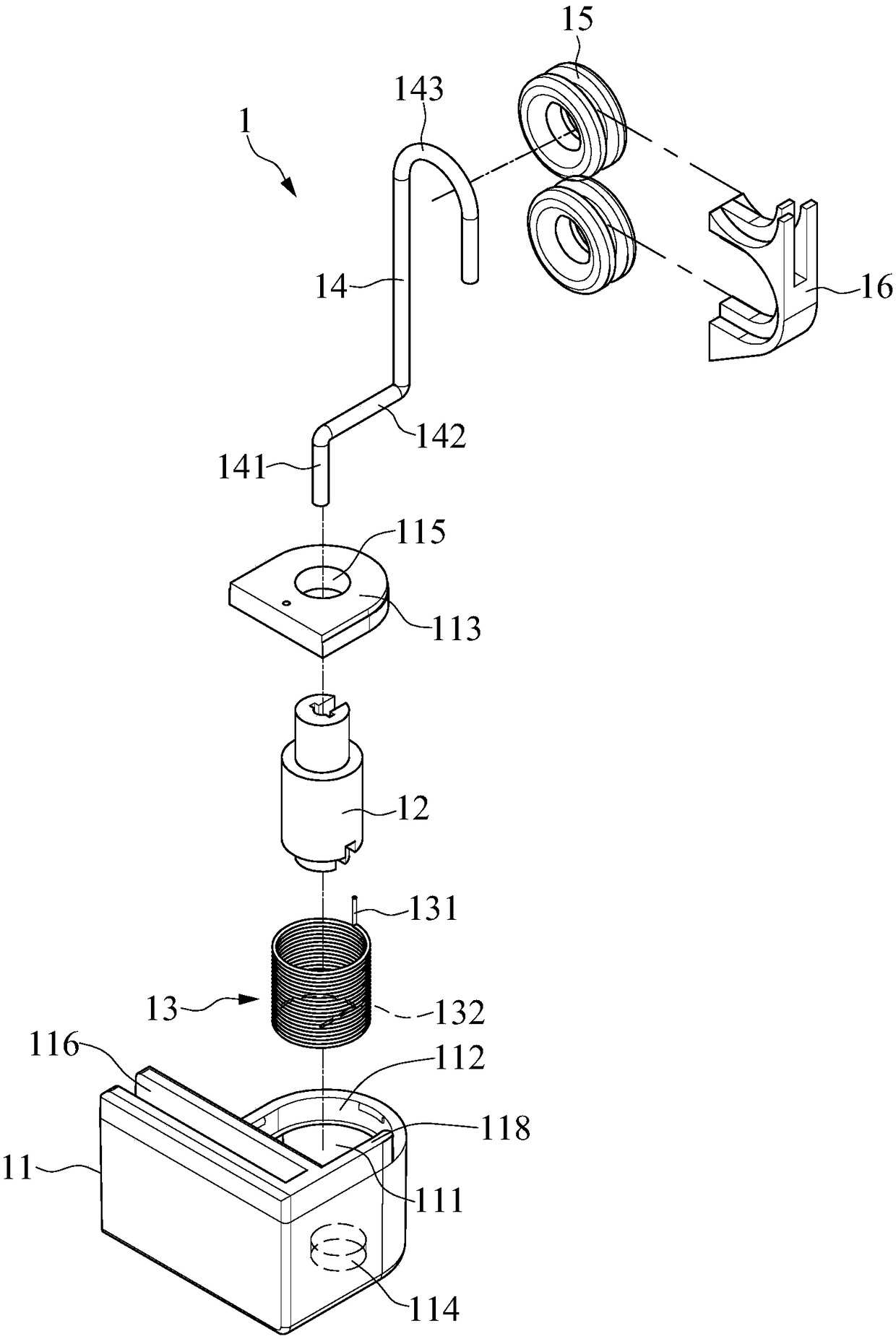
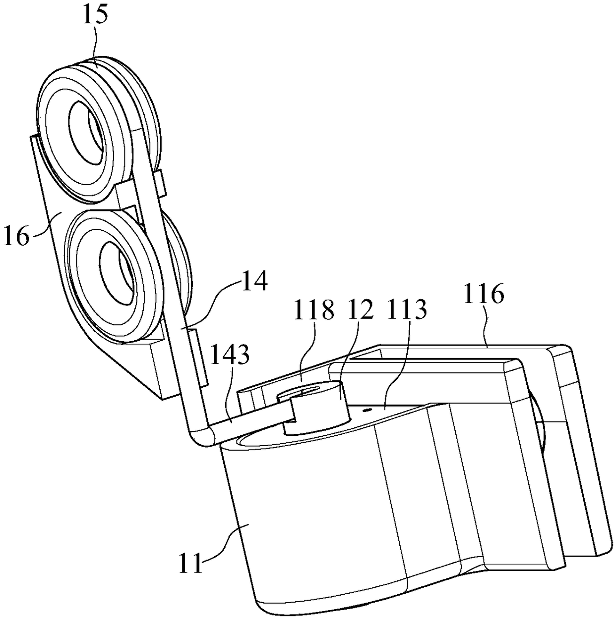
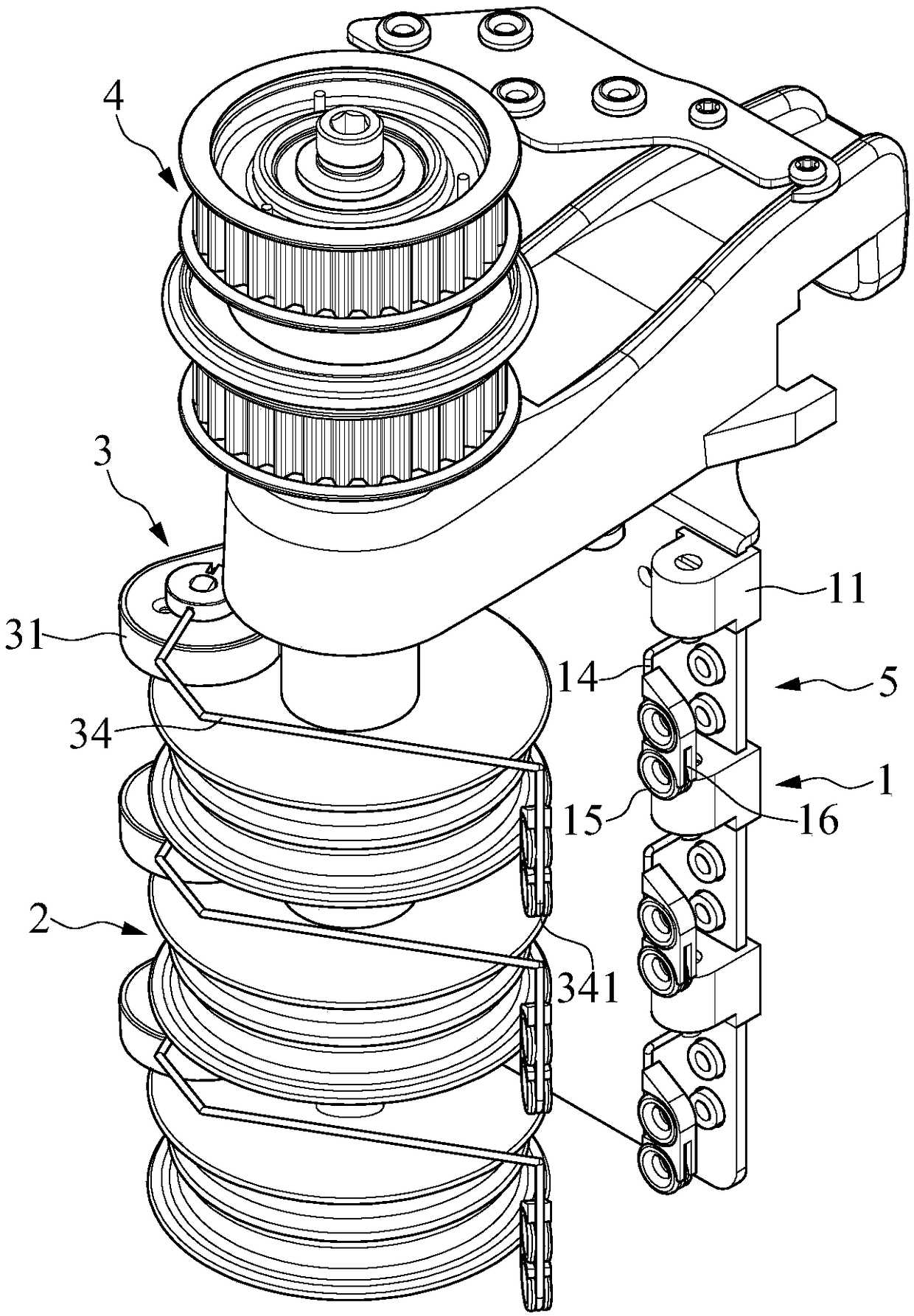
[0026] see Figure 1 to Figure 4 , the present invention provides an auxiliary yarn guide arm structure for the yarn feeding wheel of the color changing machine. The auxiliary yarn guiding arm structure 1 is used to be installed on one side of the yarn feeding wheel 2 of the color changing machine, and the number of the yarn feeding wheels 2 is not limited. It can be one, or two, three or four, etc., and the auxiliary yarn guide arm structure 1 is correspondingly provided with one, two, three or four, etc. In this embodiment, the auxiliary guide arm structure 1 There are three yarn arm structures 1 and three yarn sending wheels 2 correspondingly.

[0027] Each yarn feeding wheel 2 is correspondingly provided with a yarn guiding mechanism 3, and the yarn guiding mechanism 3 can be various single-arm yarn guiding mechanisms or double-arm yarn guiding mechanisms, and the structure of the yarn guiding mechanism 3 is not limited. The yarn guiding mechanism 3 may include a body 31 ...


PUM


Abstract

Provided is an auxiliary yarn guiding arm structure of a yarn feeding wheel of a dyeing machine. The auxiliary yarn guiding arm structure is used for being installed on one side of the yarn feeding wheel of the dyeing machine, and a yarn guiding mechanism is correspondingly arranged on the yarn feeding wheel; the auxiliary yarn guiding arm structure consists of a base body, a rotating shaft, an elastic assembly, an arm body and at least one yarn guiding piece. The rotating shaft is rotatably arranged in an accommodation space of the base body, the elastic assembly abuts against the rotating shaft, one end of the arm body is fixed to the rotating shaft, the arm body can swing between a yarn feeding position and a non-yarn feeding position, and the yarn feeding pieces are fixed to the otherend of the arm body. When the yarn feeding wheel stops feeding yarn, the yarn can spring in time.

Description

technical field [0001] The invention relates to an auxiliary yarn-guiding arm structure for a yarn-feeding wheel of a color-changing machine, in particular to an auxiliary yarn-guiding arm structure capable of bouncing the yarn in time when the yarn-feeding wheel stops eating yarn. Background technique [0002] The yarn feeding wheel of the color changing machine is a component installed on the knitting machine for yarn feeding. The existing yarn feeding wheel of the color changing machine is covered with a rubber or plastic wheel apron. Friction to transport the yarn. When the color-changing machine needs to change yarns of different colors, the yarn feeding wheel will still continue to rotate, but the knitting machine stops eating yarn. At this time, the yarn no longer has tension, and the yarn will automatically bounce off using the elastic force provided by the yarn guide arm. However, because the yarn contains yarn oil, the yarn oil will adhere to the apron, which will...

Claims


Application Information

Patent Timeline
IPC IPC(8): D04B15/54
CPCD04B15/54
Inventor 陈柏志
Owner DONGGUAN JINFU HARDWARE MACHINERY
Learn More