
Safety switch device for turning on and safely cutting off electric load

A technology for safety switches and electrical loads, applied in the direction of electric switches, electrical components, circuits, etc., can solve the problems of safety accidents, affecting the normal use of safety switches, and the failure of normal use of safety switches, and achieve the effect of preventing moisture

Active Publication Date: 2019-02-26
中通服节能技术服务有限公司
View PDF5 Cites 2 Cited by
  • Summary
  • Abstract
  • Description
  • Claims
  • Application Information

AI Technical Summary

Problems solved by technology

[0002] In systems such as power transmission and distribution, electric transmission and automatic control, it is often necessary to use electrical switches to connect and isolate power supplies. Electrical switches are widely used in power plants, substations, industrial and mining, transportation enterprises and agriculture and other units and departments. It is an indispensable electrical device in the links of electric energy production, transmission, and application. However, if the safety switch in the prior art is installed in a damp, high temperature, and dusty place, it will affect the normal use of the safety switch. When the safety switch inside When the dust in the dust increases, the safety switch cannot be used normally, resulting in safety accidents

Method used


Image

  • Safety switch device for turning on and safely cutting off electric load
  • Safety switch device for turning on and safely cutting off electric load
  • Safety switch device for turning on and safely cutting off electric load

Examples


Embodiment

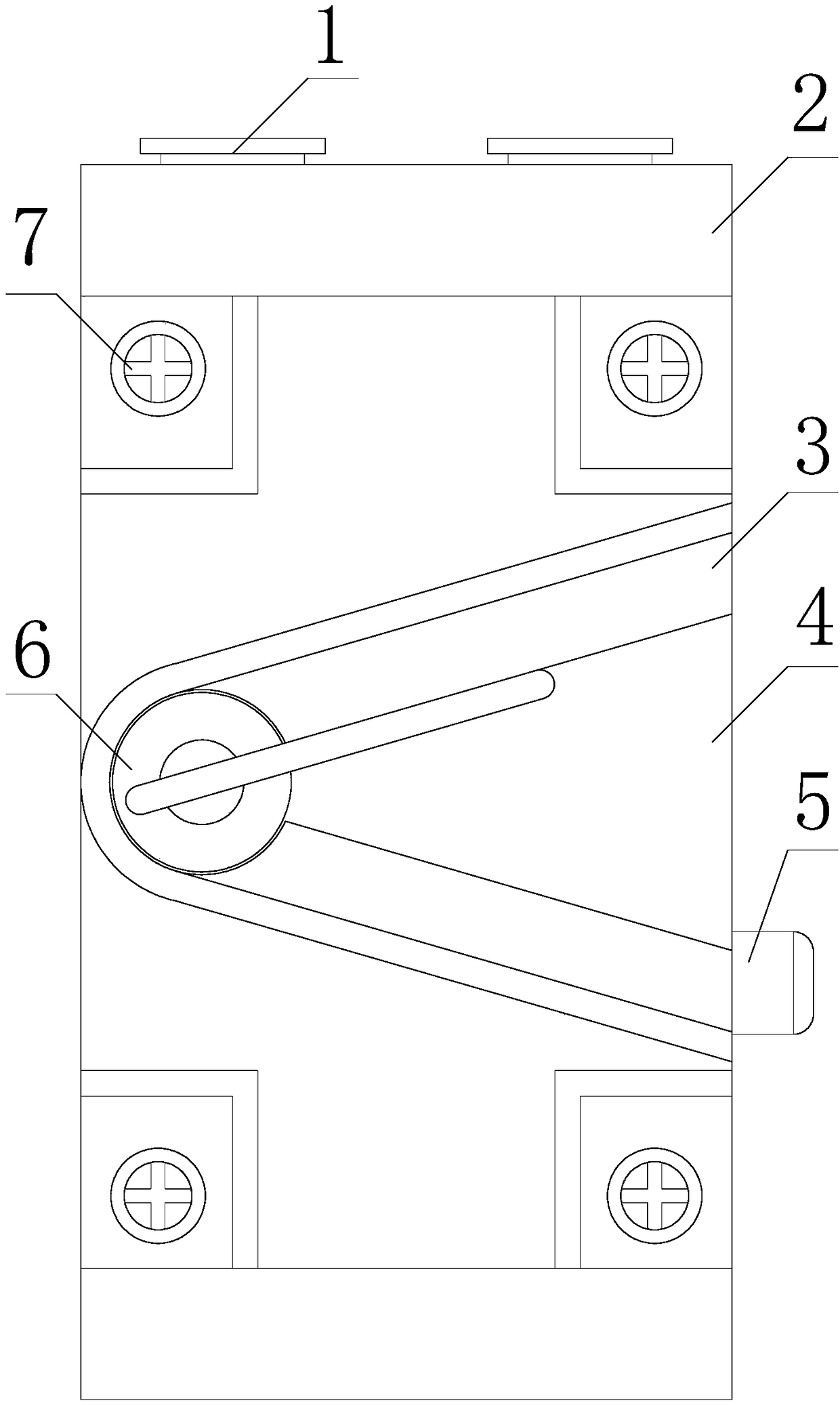
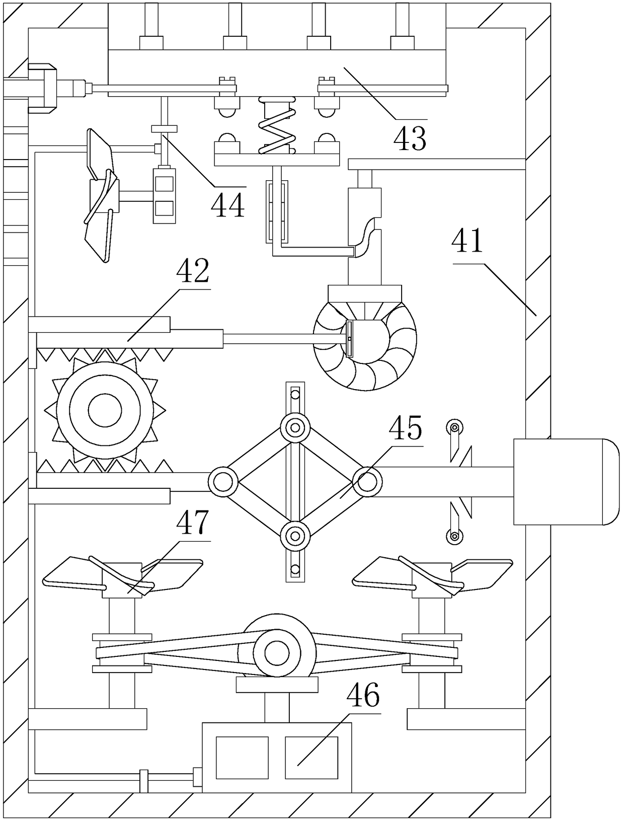
[0023] see Figure 1-Figure 4 , the present invention provides a safety switch device for switching on and safely cutting off electrical loads, the structure of which includes a connecting block 1, a mounting base 2, a limit plate 3, a safety switch host 4, an emergency cut-off button 5, an on switch 6, screws 7. The lower end of the connection block 1 is installed inside the installation seat 2, the lower surface of the installation seat 2 is attached to the upper surface of the safety switch host 4, the limit plate 3 is welded to the front surface of the safety switch host 4, and the The left end of the emergency cut-off button 5 is installed inside the right side of the safety switch host 4 by embedding, the on switch 6 is installed on the front surface of the left end of the safety switch host 4, and one end of the on switch 6 is attached to the limit plate 3, The screw 7 is threadedly connected with the front surface of the safety switch host 4 .

[0024]The safety switc...


PUM


Abstract

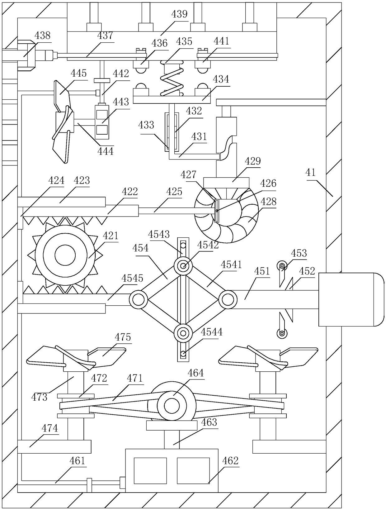
The invention discloses a safety switch device for turning on and safely cutting off an electric load, which comprises a connecting block, a mounting seat, a limit plate, a safety switch main body, anemergency cut button, a turning-on switch and a screw. The lower end of the connecting block is installed inside the mounting seat, the lower surface of the mounting seat is fitted to the upper surface of the safety switch main body, and the limit plate is welded to the front surface of the safety switch main body. The operation of the driving mechanism drives the turning-on mechanism to work, and the turning-on mechanism is responsible for turning on the electric load; at the same time, a heat dissipation mechanism is electrically operated to dissipate the heat of a turning-on element on theturning-on mechanism to ensure the normal operation of the turning-on mechanism; at this time, a power mechanism is also powered, so that a moisture-proof mechanism works to supply air to the structure inside the main body housing and prevent the structure from being damp; the dust inside the structure is also blown away to prevent the dust inside the switch from increasing, so that the safety switch can be used normally.

Description

technical field [0001] The invention relates to the field of safety switching devices for switching on and safely cutting off electrical loads, in particular to a safety switching device for switching on and safely cutting off electrical loads. Background technique [0002] In systems such as power transmission and distribution, electric transmission and automatic control, it is often necessary to use electrical switches to connect and isolate power supplies. Electrical switches are widely used in power plants, substations, industrial and mining, transportation enterprises and agriculture and other units and departments. It is an indispensable electrical device in the links of electric energy production, transmission, and application. However, if the prior art safety switch is installed in a damp, high temperature, and dusty place, it will affect the normal use of the safety switch. When the safety switch inside When the dust in the dust increases, the safety switch cannot b...

Claims


Application Information

Patent Timeline
Patent Type & Authority Applications(China)
IPC IPC(8): H01H9/04H01H9/52H01H3/32H01H3/40
CPCH01H3/32H01H3/40H01H9/04H01H9/047H01H9/52
Inventor 梁水玲
Owner 中通服节能技术服务有限公司
Learn More