
breaker

A circuit breaker and circuit technology, applied in the field of circuit protection components, can solve the problems of many components, high manufacturing cost, complex structure, etc., and achieve the effect of fewer components, low manufacturing cost and simple structure

Active Publication Date: 2020-11-03
LS INDAL SYST WUXI
View PDF9 Cites 0 Cited by
  • Summary
  • Abstract
  • Description
  • Claims
  • Application Information

AI Technical Summary

Problems solved by technology

However, due to the above-mentioned existing electronic circuit breaker adopting an electronic tripping control scheme, its structure is complex, there are many components, and the manufacturing cost is relatively high.

Method used


Image

  • breaker
  • breaker
  • breaker

Examples


Embodiment Construction

[0059] Typical embodiments embodying the features and advantages of the present invention will be described in detail in the following description. It should be understood that the present invention can have various changes in different embodiments without departing from the scope of the present invention, and that the description and drawings therein are illustrative in nature and not intended to limit the present invention. invention.

[0060] In the following description of various exemplary embodiments of the invention, reference is made to the accompanying drawings, which form a part hereof, and in which are shown by way of example different exemplary structures, systems, and embodiments in which aspects of the invention may be implemented and steps. It is to be understood that other specific arrangements of components, structures, exemplary means, systems and steps may be utilized and structural and functional modifications may be made without departing from the scope o...


PUM


Abstract

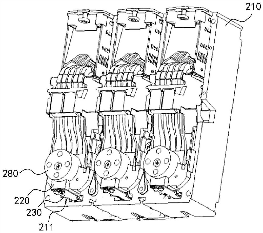
The invention discloses a circuit breaker. The circuit breaker comprises a housing body, a heat conducting block, a dialing rod, double metal sheets and a mechanical tripping device. The housing bodycomprises a first side and a second side. A composite terminal connected with a circuit is arranged on the first side. The heat conducting block is arranged on the first side of the housing body and connected with the composite terminal. The dialing rod is rotatably arranged on the second side of the housing body. Each double metal sheet comprises a positioning end and a free end. The positioningends are connected to the heat conducting block. The free ends pass through the housing body and extend to the dialing rod. The mechanical tripping device is installed on the second side of the housing body. The heat conducting block is capable of conducting heat of the composite terminal to the double metal sheets. When the current of the circuit is overloaded, heat is increased so that the double metal sheets are bent to drive the dialing rod to rotate, and when the dialing rod rotates to a triggering angle, the mechanical tripping device is triggered to move. According to the invention, thedouble metal sheets are bent after being heated to drive the dialing rod to rotate, thereby achieving tripping of the circuit breaker. Compared with the current electronic type circuit breaker, the structure is simple, the components are fewer, the cost is quite low and different requirements can be met.

Description

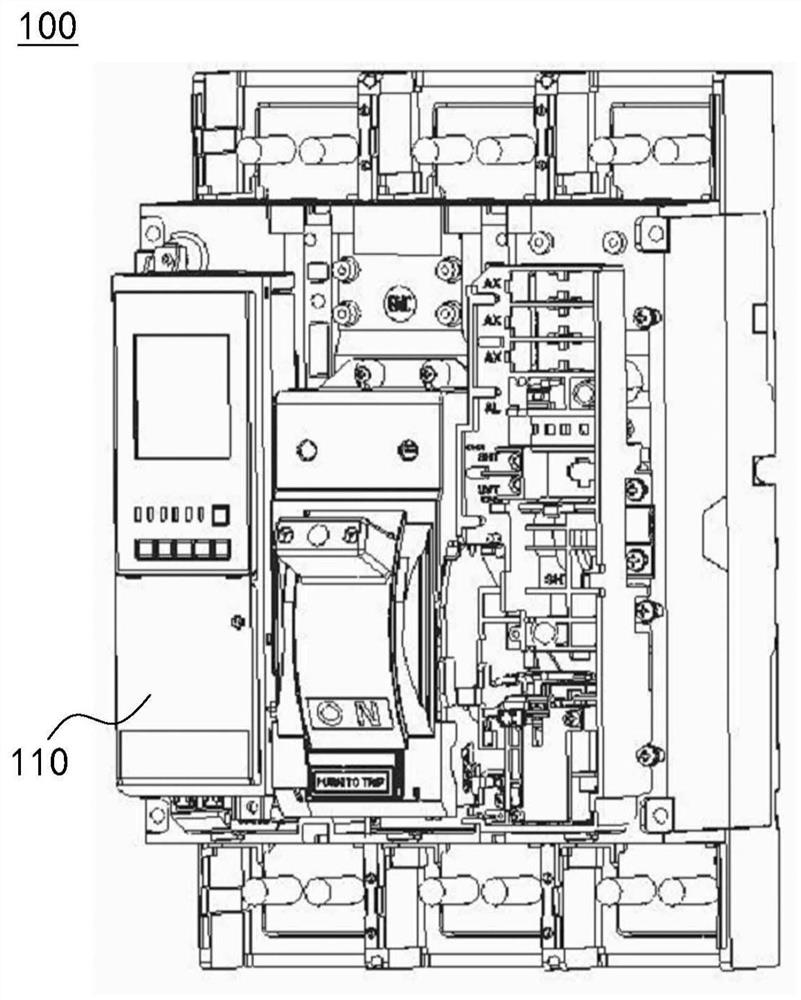
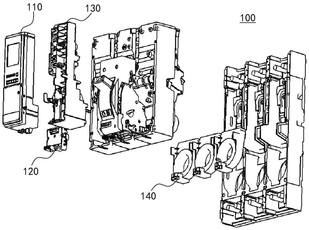
technical field [0001] The present invention relates to the technical field of circuit protection components, in particular to a circuit breaker. Background technique [0002] A circuit breaker refers to a switching device that can close, carry and break current under normal circuit conditions, and can close, carry and break current under abnormal circuit conditions within a specified time. It can be used to distribute electrical energy. Frequent starting of asynchronous motors, protection of power lines and motors, etc., has a wide range of applications. Among them, the circuit can be automatically cut off when the above-mentioned equipment is overloaded or short-circuited. Moreover, there is generally no need to change parts after breaking the fault current. [0003] refer to figure 1 and figure 2 , which respectively show a three-dimensional structure schematic diagram and an exploded schematic diagram of an existing electronic circuit breaker 100, which generally in...

Claims


Application Information

Patent Timeline
Patent Type & Authority Patents(China)
IPC IPC(8): H01H71/16H01H71/40
CPCH01H71/16H01H71/40
Inventor 陆惠芳宋重千
Owner LS INDAL SYST WUXI
Learn More