Dipole antenna oscillator

A dipole antenna and vibrator technology, which is applied in the field of innovative structure of dipole antenna vibrator, can solve the problems of excessive deviation, electrical difference, and impact on performance in the interval correspondence, and improve the quality and performance of dipole antenna vibrator , better component configuration accuracy, conducive to the effect of mass production

Inactive Publication Date: 2019-02-26
WHA YU IND CO LTD +1
View PDF4 Cites 2 Cited by
  • Summary
  • Abstract
  • Description
  • Claims
  • Application Information

AI Technical Summary

Problems solved by technology

[0002] In the early days when the industry designed dual-polarized dipole antennas, most of them used two crossed feeders as the conductor connection interface fed into the coaxial line, and adjusted the matching value by changing the length and width of the feeders; Or, there is also a design in the industry that another section of conductive frame is connected to the end of the coaxial line as the feed-in structure of the dipole antenna; this design not only needs to increase the disadvantages of additional assembly cost and material cost, but also because of the assembly process The problem of electrical difference caused by instability
[0003] In view of the above-mentioned problems, some improvements have been proposed in the relevant industries, such as making the radiation frame of each unit at the upper end of the support frame consist of two coupling arms with an angle configuration relationship, and adjacent to the coupling arms of the radiation frame. There is an interval configuration relationship between them; this kind of dipole antenna dipole shape is still found in practical application experience, because after the two coupling arms with an angle configuration relationship in each unit radiation frame are formed, the surface between the two coupling arms Flattening accuracy is prone to bending and deformation deviations. As a result, the corresponding relationship between the coupling arms adjacent to the radiation frame after its assembly is relatively easy to cause excessive deviations and affect performance. This is really worthy of concern. Important technical issues for the industry to think about breakthroughs

Method used


Image

  • Dipole antenna oscillator
  • Dipole antenna oscillator
  • Dipole antenna oscillator

Examples


Embodiment Construction

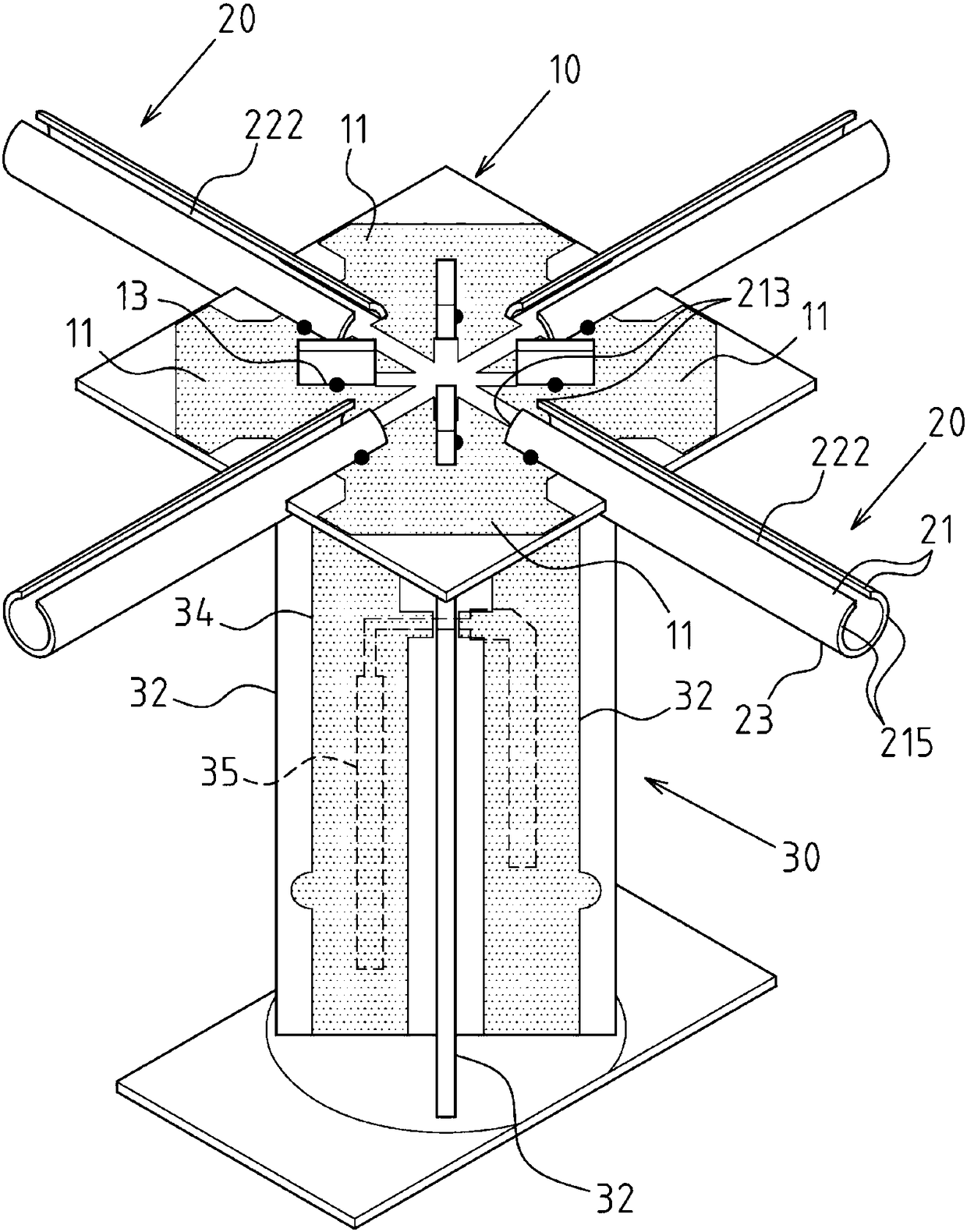
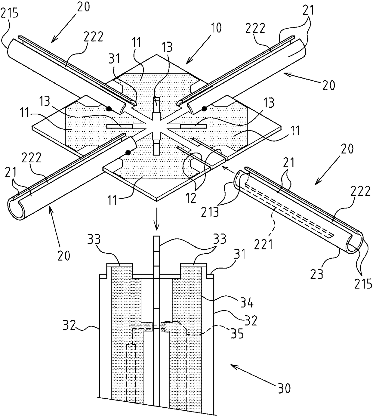
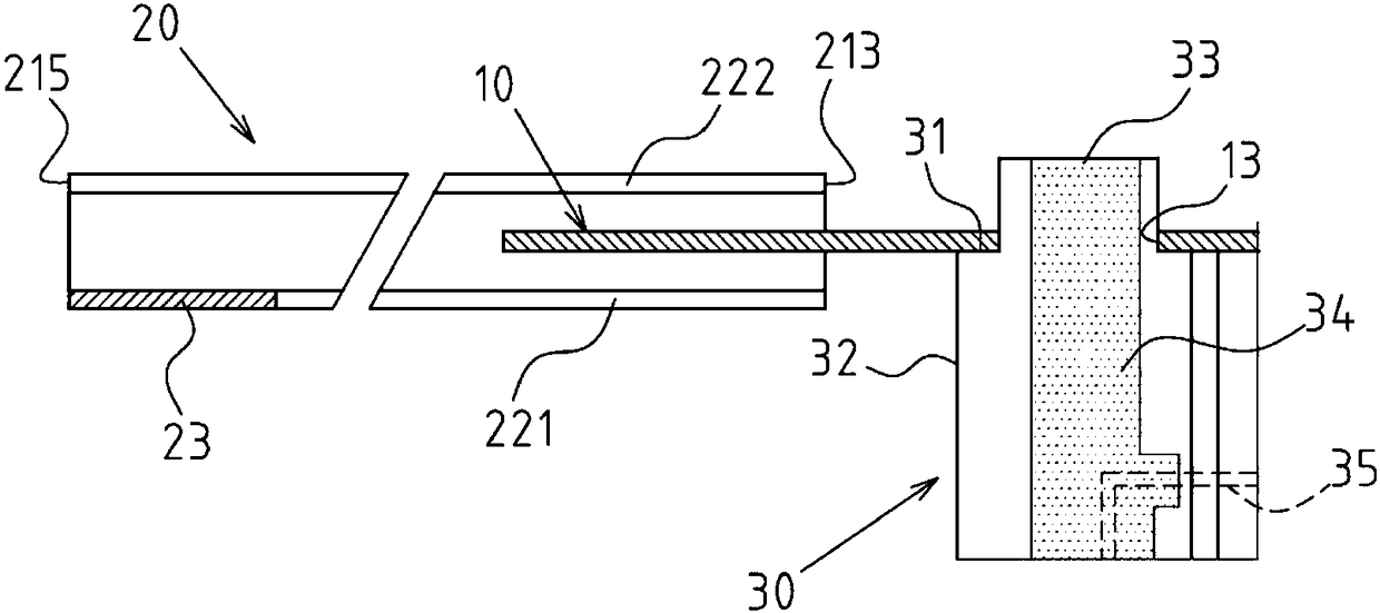
[0015] see figure 1 , 2 3. The dipole antenna vibrator of the present invention includes the following components: a power distribution component 10, which is provided with a plurality of power distribution blocks 11 distributed at intervals; a plurality of radiation frames 20, which are arranged on the sides of the power distribution component 10 and are symmetrically spaced Configuration form, and there is an included angle configuration relationship between the two radiation frames 20 adjacent to each other (in this example, a 90-degree angle configuration relationship), and each radiation frame 20 includes: two coupling arms 21, which are arranged in a spaced relationship with each other , the two coupling arms 21 are respectively provided with an electrical connection end 213 and are respectively electrically connected with the two power distribution blocks 11 adjacent to the power distribution member 10, each coupling arm 21 also has an extension end 215, and the two cou...


PUM


Abstract

The present invention discloses a dipole antenna oscillator. The dipole antenna oscillator comprises a power distribution member provided with a plurality of power distribution blocks; and a pluralityof radiation racks arranged at the circumference side of the power distribution member, each radiation rack comprises two coupling arms arranged at intervals and respectively provided with electricalconnection ends connected with the adjacent power distribution blocks, first and second isolation gaps are formed between the two coupling arms, the portion from the electrical connection ends to theextension ends of the coupling arms forms a current path with a quarter wave length, a half wave length or a full wave length corresponding to a first isolation gap tail end to allow the length of the current path formed at the second isolation gap tail end to be larger than the length of the current path formed at the first isolation gap tail end; the two adjacently arranged radiation racks arerespectively provided with the coupling arms, the coupling arms and the power distribution member are electrically connected with the corresponding same power distribution block to commonly constructand form the radiation member.

Description

technical field [0001] The invention relates to an antenna; in particular, it refers to an innovative structure of a dipole antenna vibrator. Background technique [0002] When designing dual-polarized dipole antennas in the early days, most of the industry used two crossed feeders as the conductor connection interface fed into the coaxial line, and adjusted the matching value by changing the length and width of the feeders; Alternatively, there is also a design in the industry that another section of conductive frame is connected to the end of the coaxial line as the feed-in structure of the dipole antenna; The instability caused by electrical differences. [0003] In view of the above-mentioned problems, the relevant industry has proposed some improvements before, such as making each unit radiation frame at the upper end of the support frame body composed of two coupling arms with an angle configuration relationship, and adjacent to the coupling arms of the radiation fram...

Claims


Application Information

Patent Timeline
Patent Type & Authority Applications(China)
IPC IPC(8): H01Q1/36H01Q1/12H01Q1/50H01Q21/00
CPCH01Q1/12H01Q1/36H01Q1/50H01Q21/00
Inventor 郭李瑞
Owner WHA YU IND CO LTD
Why Eureka
Try Eureka