Network loop detection method and device

A network loop and detection method technology, applied in the field of communication, can solve problems such as uncertain equipment

Active Publication Date: 2019-02-26
RUIJIE NETWORKS CO LTD
View PDF7 Cites 7 Cited by
  • Summary
  • Abstract
  • Description
  • Claims
  • Application Information

AI Technical Summary

Problems solved by technology

[0007] The purpose of the present invention is to provide a method and device for detecting network loops, which solves the problem in the prior art that only the network loops can be detected, and the related equipment causing the network loops cannot be determined.

Method used


Image

  • Network loop detection method and device
  • Network loop detection method and device
  • Network loop detection method and device

Examples


Embodiment Construction

[0058] The following will clearly and completely describe the technical solutions in the embodiments of the present invention in conjunction with the accompanying drawings in the embodiments of the present invention. Obviously, the described embodiments are only some of the embodiments of the present invention, not all of them. Based on the embodiments of the present invention, all other embodiments obtained by persons of ordinary skill in the art without making creative efforts belong to the protection scope of the present invention.

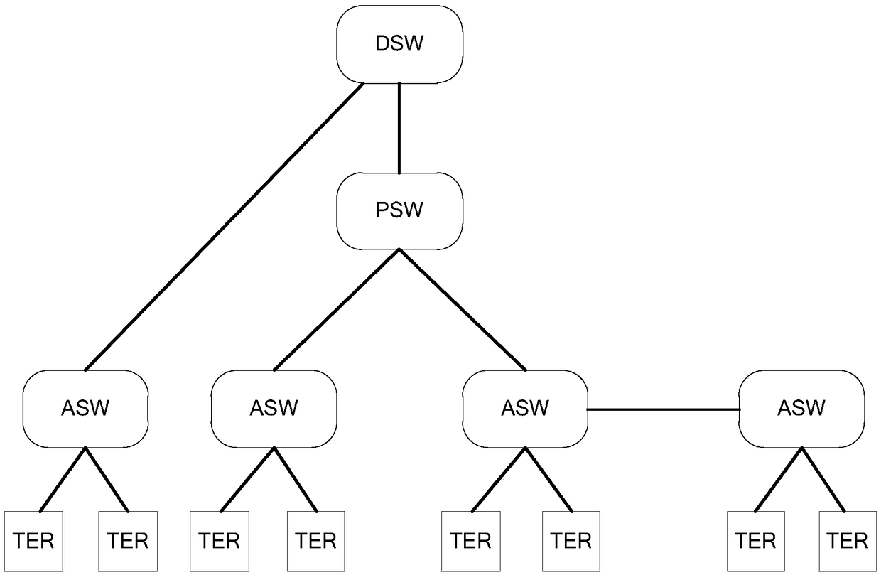
[0059] A network can usually be divided into a core layer, an aggregation layer, and an access layer. Devices deployed at each layer are usually called: core devices, aggregation devices, and access devices. With the core device as the root node, the aggregation device and access device can refer to figure 2 As shown, the core equipment involved is represented by DSW, the aggregation device is represented by PSW, the access device is represent...


PUM


Abstract

The invention discloses a network loop detection method and device. The method comprises the steps that a local network device receives the identification information of a peer network device and theidentification information of an upstream network device of the peer network device, which are sent by the peer network device; the identification information of the local network device is compared with the identification information of the upstream network device of the peer network device, and the identification information of the upstream network device of the local network device is comparedwith the identification information of the peer network device, so as to determine whether the local network device and the peer network device have an upstream-downstream relation: determining that the network loop occurs when there is no upstream-downstream relation. The detection method can be used to determine the relevant network equipment that constitutes the network loop, so that the maintenance personnel can quickly locate loop faults and improve the processing efficiency of the network loop.

Description

technical field [0001] The invention relates to the technical field of communications, in particular to a method and device for detecting network loops. Background technique [0002] In a large-scale network environment, due to improper configuration of network equipment or hardware damage of network equipment, incorrect connection of network physical topology, or virus attack on the network, network loops become one of the most prone to failures. Network loops are network The device has received the message sent by itself, such as Figure 1A , 1B A schematic diagram of a network loop is shown. [0003] in, Figure 1A and Figure 1B Both include network device 1, network device 2, and network device 3, in Figure 1A Network device 1 is connected to network device 2 through port 1, and network device 1 is connected to network device 3 through port 2. [0004] Since network loops will cause network devices to continuously copy and forward broadcast, multicast and unknown pa...

Claims


Application Information

Patent Timeline
Patent Type & Authority Applications(China)
IPC IPC(8): H04L12/26H04L12/24H04L12/705H04L45/18
CPCH04L41/0677H04L43/08H04L43/50H04L45/18
Inventor 刘熙
Owner RUIJIE NETWORKS CO LTD
Why Eureka
Try Eureka