Washing machine

A cleaning machine and cleaning mechanism technology, applied in the field of cleaning machines, can solve problems such as flushing, and achieve the effects of enhanced cleaning effect, good cleaning effect, and increased impact force and frictional force

Pending Publication Date: 2019-03-01
NINGBO FOTILE KITCHEN WARE CO LTD
View PDF9 Cites 2 Cited by
  • Summary
  • Abstract
  • Description
  • Claims
  • Application Information

AI Technical Summary

Problems solved by technology

Because it sets two spray arms and sets the direction of the nozzle so that the water flow sprayed from the spray hole can form a circular rotating water flow, and the spray arms at both ends exert the same force on the fruits and vegetables, so that the fruits and vegetables can be sprayed in the air. The vegetable basket rotates in a certain direction. Relative to the sink body and the water flow, the fruits and vegetables are in motion. The water flow can wash every surface of the fruits and vegetables to be cleaned. At the same time, ultrasonic generators are installed on both sides of the spray arm. Obtain a better cleaning effect; but it needs to be provided with two water pumps and two spray arms, for this reason, further improvement is needed, and at the same time only a single rotating spray arm is used to clean the object to be cleaned (fruits and vegetables or fruits and vegetables). There are some dead spots that cannot be washed by the water sprayed from the rotating spray arm

Method used


Image

  • Washing machine
  • Washing machine
  • Washing machine

Examples


Embodiment 1

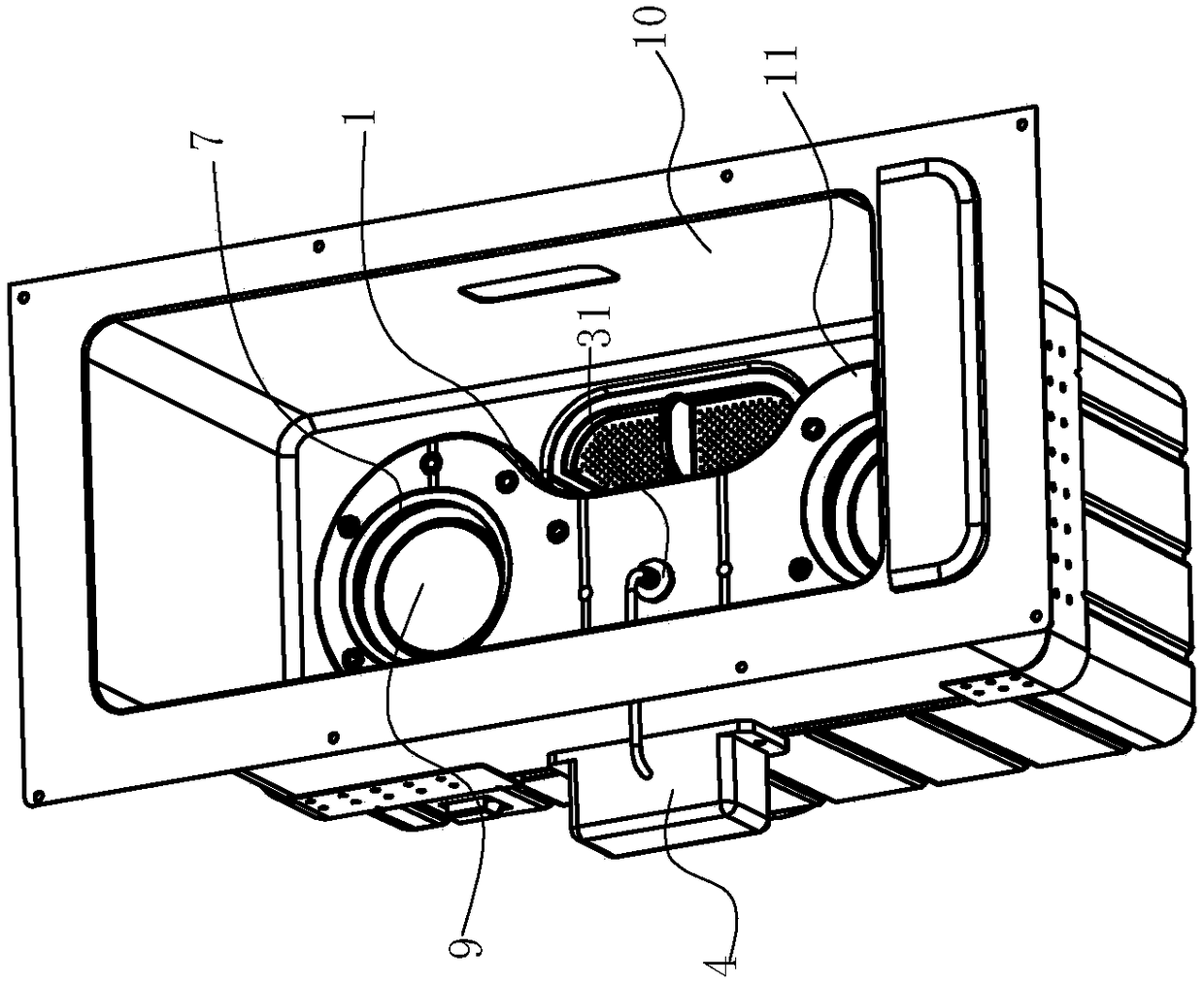
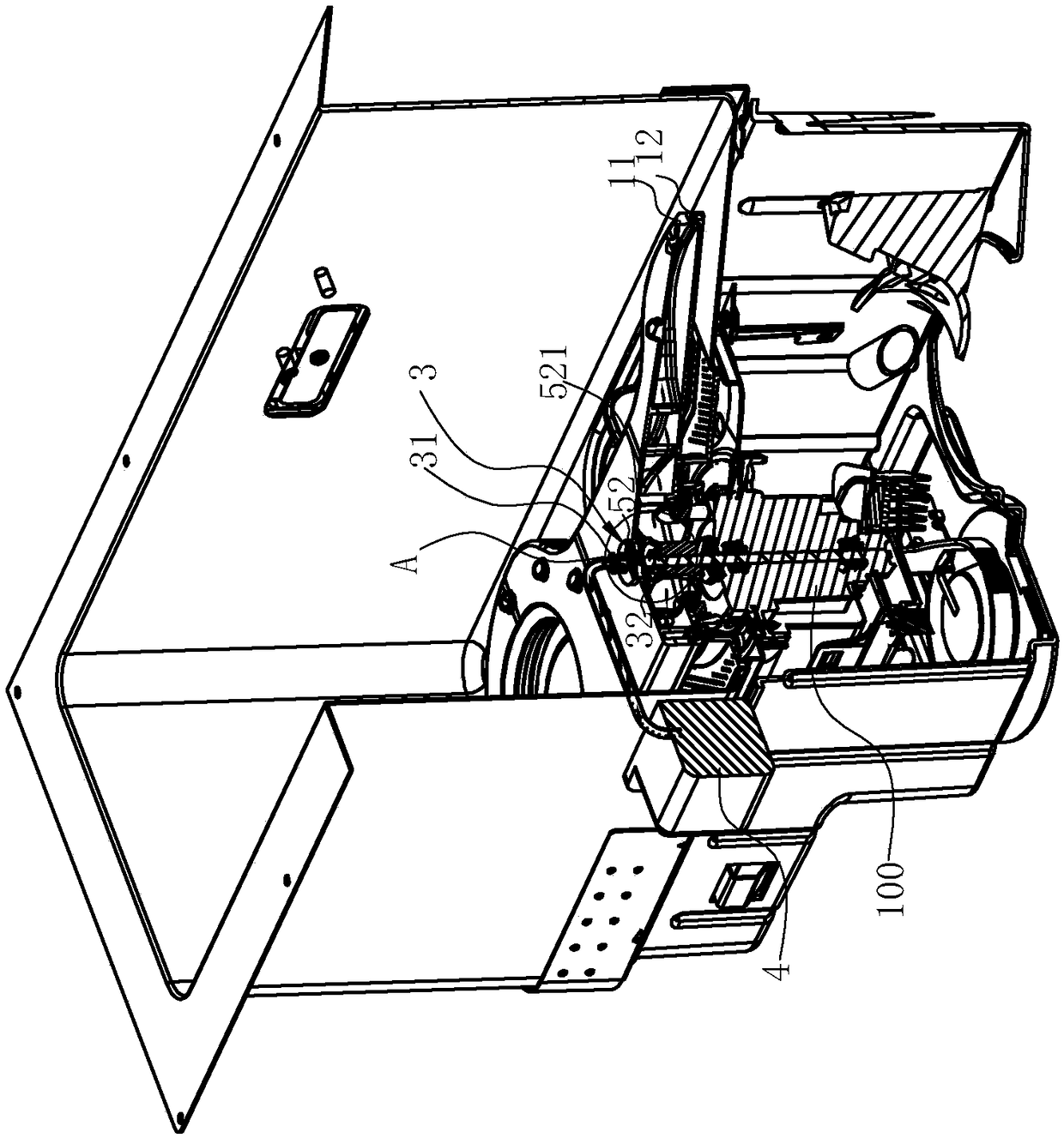
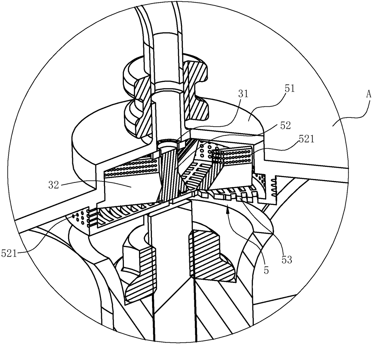
[0025] see Figure 1 ~ Figure 4 , the cleaning machine of the present invention is designed to be particularly suitable for the sink type cleaning machine with a long and narrow water tank, especially for the cleaning of fruits and vegetables, but in fact it can also be applied to ordinary sink type cleaning machines, as well as European type cleaning machines with front doors and Drawer washing machine.

[0026] The following takes the fruit and vegetable cleaning machine as an example to expand the description:

[0027] This fruit and vegetable cleaning machine includes a box body 8 and a cleaning mechanism located in the box body 8. The cleaning mechanism at least includes a spray arm 2 and a water pump 100 that are arranged at the bottom of the box body 1 and are fixed relative to the box body 1. The water pump 100 is arranged At the bottom of the box body 8 , the spray arm is used as a water outlet part of the water pump 100 to spray the water pumped out by the water pum...

Embodiment 2

[0036] The structure is basically similar to that of Embodiment 1, the difference is that the flow channel 2 is a radial flow channel, that is, it is divided into three sub-channels, namely the third flow channel 23, the fourth flow channel 24 and the fifth flow channel 25, each At least three spray holes are arranged on the wall corresponding to the sub-runners to control the spraying pressure of each bundle of sub-runners to be consistent.


PUM


Abstract

The invention relates to a washing machine. The washing machine comprises a tank and a washing mechanism arranged in the tank, wherein the washing mechanism at least comprises a spraying arm arrangedon the bottom of the tank and fixed relative to the tank, and the inside of the spraying arm is hollow and forms flowing channels. The washing machine is characterized in that an inflating hole communicating with the flowing channels is formed in the top wall of the spraying arm, and the inflating hole is connected with an external air supply device. Compared with the prior art, the washing machine has the advantages that an air inflating cavity communicating with the flowing channels is arranged in the wall face of the spraying arm, thus air introduced from the inflating hole of the air inflating cavity can generate air bubbles, the water mixed with the abundant air bubbles can be sprayed to washed objects from spraying holes of the spraying arm, cracking is generated, then the instantaneous air explosion phenomenon is formed, so that the radioactive impact force is formed, thus the area and probability for directly flushing the washed objects are increased, further, the clean washingspeed is accelerated, and the spraying dead angles of the spraying arm are effectively avoided.

Description

technical field [0001] The invention relates to the field of household dishwashers, in particular to a washing machine. Background technique [0002] Along with improving day by day of people's living standard, dishwasher more and more enters family as a kind of kitchen appliance product. Dishwashers currently on the market are generally divided into three types: table type, cabinet type, and tank type. Among them, the table type dishwasher is an integral independent structure, which is generally placed on the table for use; , but needs to be embedded in the kitchen cabinet for use; the sink dishwasher is combined with the sink and is generally installed in the kitchen cabinet for use. [0003] The above-mentioned various forms of dishwashers generally use a water pump to lift water and spray it to the fruits and vegetables in the cleaning space so as to achieve the cleaning effect. For example, the Chinese patent "Microcomputer Light-controlled Automatic Dishwasher" with ...

Claims


Application Information

Patent Timeline
Patent Type & Authority Applications(China)
IPC IPC(8): A47J43/24
CPCA47J43/24
Inventor 徐慧王吉茅忠群诸永定
Owner NINGBO FOTILE KITCHEN WARE CO LTD
Why Eureka
Try Eureka