
Chest drainage catheter

A catheter and thoracic technology, applied in the field of thoracic drainage catheter, can solve the problems of patient pain, affecting normal use, tissue protein blockage, etc., and achieve the effect of preventing blockage

Pending Publication Date: 2019-03-01
西登彬
View PDF5 Cites 4 Cited by
  • Summary
  • Abstract
  • Description
  • Claims
  • Application Information

AI Technical Summary

Problems solved by technology

[0005] Existing chest drainage catheters, especially central venous catheters, are easily blocked by tissue protein at the end during use, thereby affecting normal use, and when the drainage catheter moves in the body or when the patient breathes or coughs, it is easy to cause pain to the patient

Method used


Image

  • Chest drainage catheter
  • Chest drainage catheter

Examples


Embodiment 1

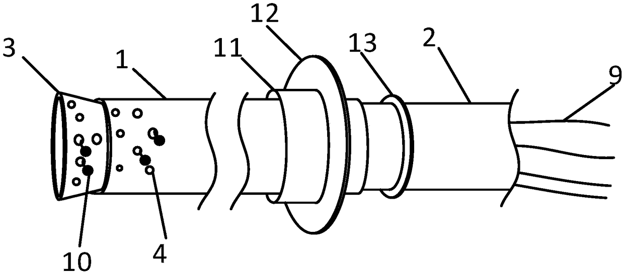
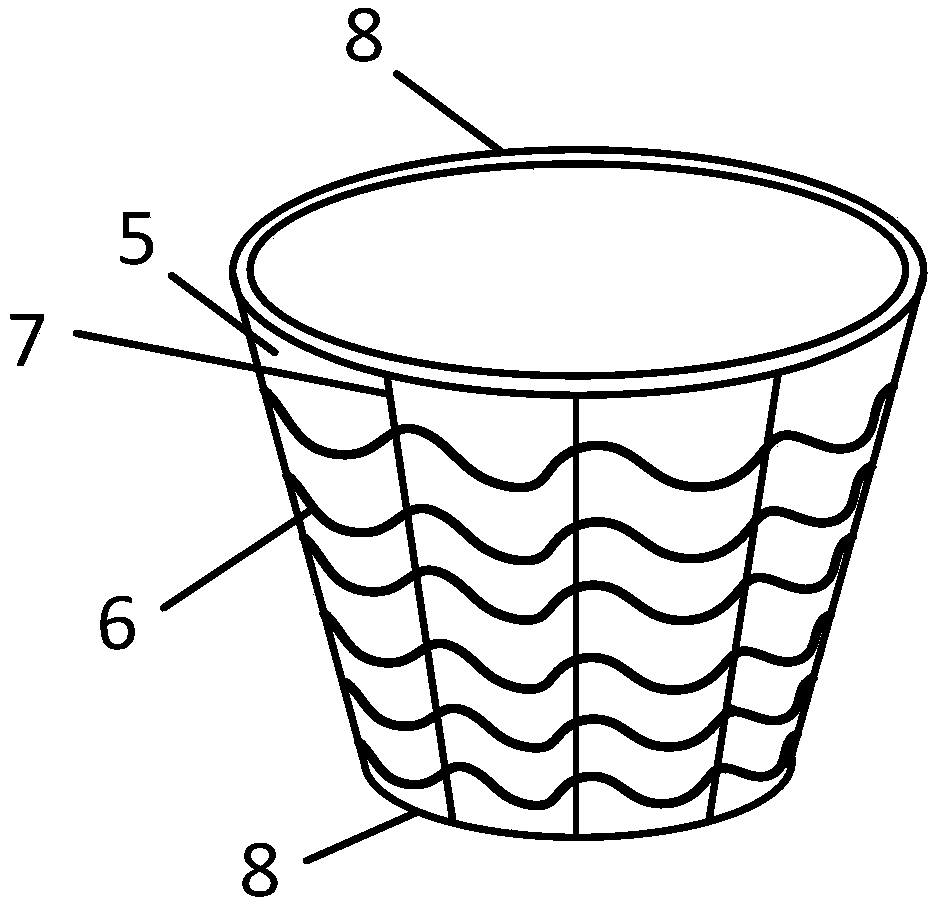
[0028] This embodiment provides a chest drainage catheter, such as Figure 1-2 As shown, the chest drainage catheter includes an outer tube 1, an inner tube 2 and a suction head 3, the suction head 3 is connected to the front end of the inner tube 2, and the outer tube 1 is sleeved on the front part of the inner tube 2 The inner tube 2 can slide back and forth in the outer tube 1, the suction head 3 has a contracted state and an expanded state, and the suction head 3 is in a contracted state when accommodated inside the outer tube 1, so After the inner tube 2 slides forward along the outer tube 1, the suction head 3 is in an expanded state in which the inner diameter gradually expands from the rear to the front. A suction hole 4 is opened, and the suction head 3 includes an elastic sleeve 5, a plurality of wave spring coils 6 whose diameters are successively increased and radially compressible are embedded in the elastic sleeve 5 from back to front, and connect adjacent A plu...

Embodiment 2

[0031] This embodiment provides suction head, such as figure 2 As shown, the opening with a larger diameter and the opening with a smaller diameter of the suction head 3 are circular and supported by an elastic resin ring 8 embedded in the elastic sleeve 5, and the two elastic resin rings 8 pass through the connecting wire 7 Connected with adjacent wave coils 6, the elastic sleeve 5 is flexible latex or rubber. By arranging the elastic resin ring, the two ends of the suction head can be kept round, so that it can be smoothly stored in and released from the outer tube.

Embodiment 3

[0033] This embodiment provides an outer tube and an inner tube, such as figure 1 As shown, the length of the outer tube 1 is 10-40cm, the length of the inner tube 2 is greater than that of the outer tube 1, and the outer wall of the inner tube 2 is provided with a stop ring 13 for limiting the movement of the outer tube 1, When the rear end of the outer tube 1 is pulled back to the limit ring 13 , the suction head 3 is completely exposed to the outside of the outer tube 1 . The inner tube 2 and the outer tube 1 are each independently a resin tube. The excessive release of the suction head 3 can be prevented by setting the limit ring, and the inner tube and the outer tube can have certain elasticity and rigidity through the resin tube, and can smoothly enter the chest cavity.


PUM


Abstract

The embodiment of the invention discloses a chest drainage catheter. The chest drainage catheter comprises an outer tube, an inner tube and a suction head, wherein the outer tube sleeves the peripheryof the front of the inner tube, the suction head is connected to the front end of the inner tube, the inner tube can slide front and back in the outer tube, the suction head has the contraction stateand the expansion state, the suction head is in the contraction state when accommodated in the outer tube, the suction head is in the expansion state with the inner diameter enlarged in the sequencefrom rear to front after the inner tube forwards slides along the outer tube, and the suction head comprises an elastic sleeve, wavy spring rings and a plurality of connecting wires for connecting theadjacent wavy spring rings. The chest drainage catheter provided by the embodiment of the invention comprises the outer tube, the inner tube and the suction head, the suction head is accommodated inthe inner tube in a contraction manner under the effect of the outer tube and can expand out from the outer tube, so that blockages in the suction head and the inner tube can be cleared through contraction and expansion, and therefore, the blockage of the chest drainage catheter is effectively prevented.

Description

technical field [0001] The invention relates to the technical field of medical devices, in particular to a chest drainage catheter. Background technique [0002] Closed thoracic drainage is to put one end of the drainage tube into the chest cavity, and the other end is connected to a water-sealed bottle lower than its position, so as to discharge gas or collect fluid in the chest cavity, so that the lung tissue can reopen and restore function. A treatment method is widely used in the drainage of hemothorax, pneumothorax, empyema and after thoracotomy, and plays a very important role in the treatment of diseases. [0003] The prior art discloses a chest drainage device, which includes a drainage tube. One end of the drainage tube used to be inserted into the chest cavity is a drainage end, and the other end is a discharge end. The part of the drainage tube close to the drainage end is fixedly connected with a capsule that wraps around its outer wall , the capsule is a hollow...

Claims


Application Information

Patent Timeline
Patent Type & Authority Applications(China)
IPC IPC(8): A61M25/00
CPCA61M25/0017A61M25/0021A61M2025/0004
Inventor 西登彬
Owner 西登彬
Learn More