Supercharge Your Innovation With Domain-Expert AI Agents!

Cleaning and disinfection tank device for endoscope room

A technology for cleaning, disinfecting and cleaning tanks, which is applied in the field of medical devices, and can solve problems such as the inability to fix the position of medical devices, the inability to quickly clean medical devices, and the inconvenient adjustment of medical devices, etc., to achieve the effect of rapid cleaning

Inactive Publication Date: 2019-03-01
徐海艳
View PDF11 Cites 0 Cited by
  • Summary
  • Abstract
  • Description
  • Claims
  • Application Information

AI Technical Summary

Problems solved by technology

[0002] An endoscope is a detection instrument that integrates traditional optics, ergonomics, precision machinery, modern electronics, mathematics, and software. It has image sensors, optical lenses, light source lighting, and mechanical devices. The internal channel of the endoscope is used for cleaning. The disinfection tank cleans and disinfects the medical instruments used. For example, the patent application publication number 201810162672.0 discloses a cleaning and disinfection tank device for endoscope room, including a device body, a protective rubber cover and a protective rubber tank. The device body The bottom is fixedly equipped with a load-bearing fixing groove, and the middle of the top of the bearing-fixing groove is fixedly installed with a cleaning fixing groove. The left end of the bearing-fixing groove is provided with an article storage box, and the right end of the load-bearing fixing groove is provided with a fixed storage box. , but during the use of the above patents, the position of the medical device to be cleaned and disinfected cannot be fixed during cleaning, and it is not convenient to adjust according to the size of the medical device, and it is impossible to quickly clean the medical device

Method used


Image

  • Cleaning and disinfection tank device for endoscope room
  • Cleaning and disinfection tank device for endoscope room

Examples


Embodiment Construction

[0014] The following will clearly and completely describe the technical solutions in the embodiments of the present invention with reference to the accompanying drawings in the embodiments of the present invention. Obviously, the described embodiments are only some, not all, embodiments of the present invention. Based on the embodiments of the present invention, all other embodiments obtained by persons of ordinary skill in the art without making creative efforts belong to the protection scope of the present invention.

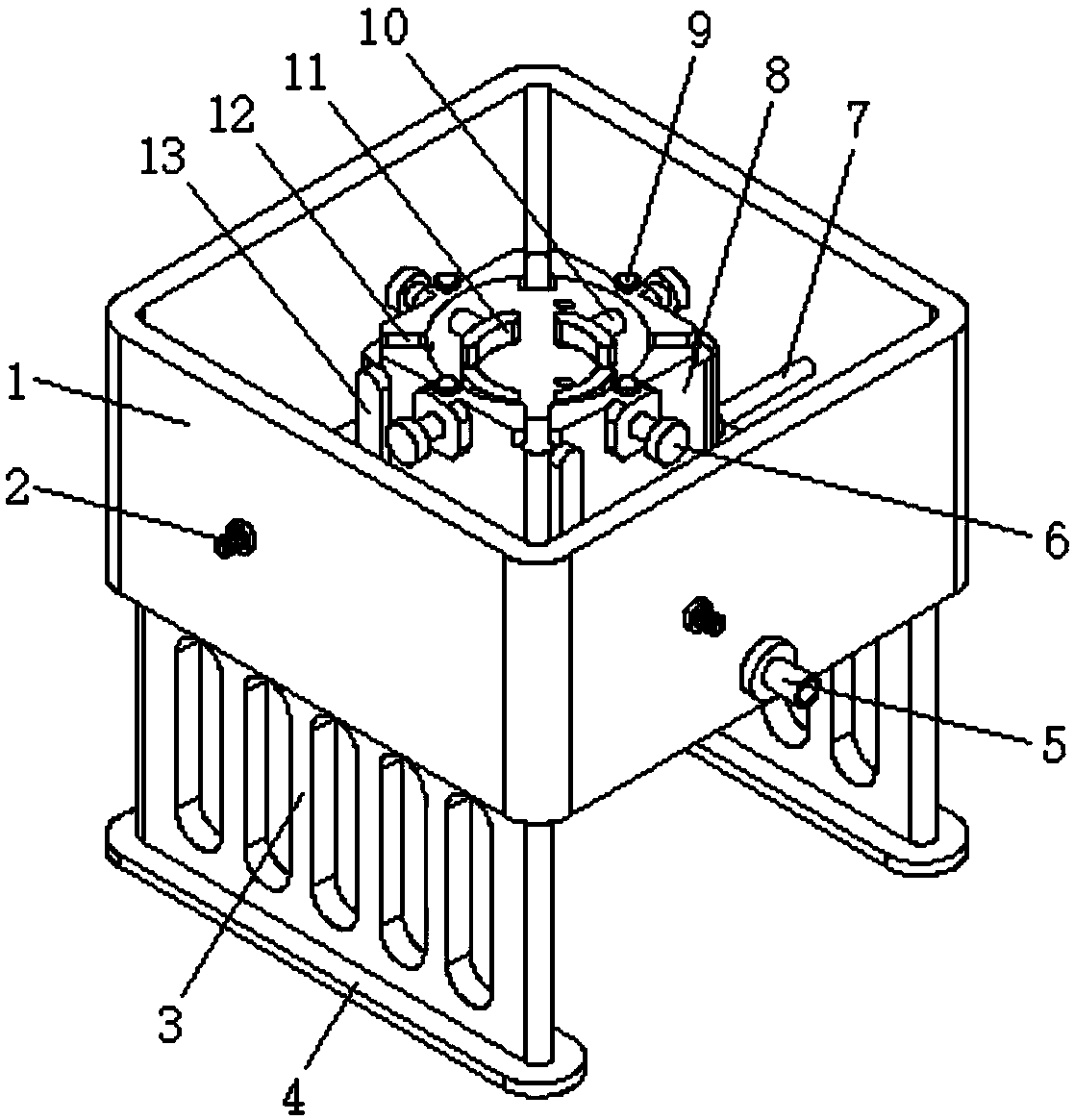
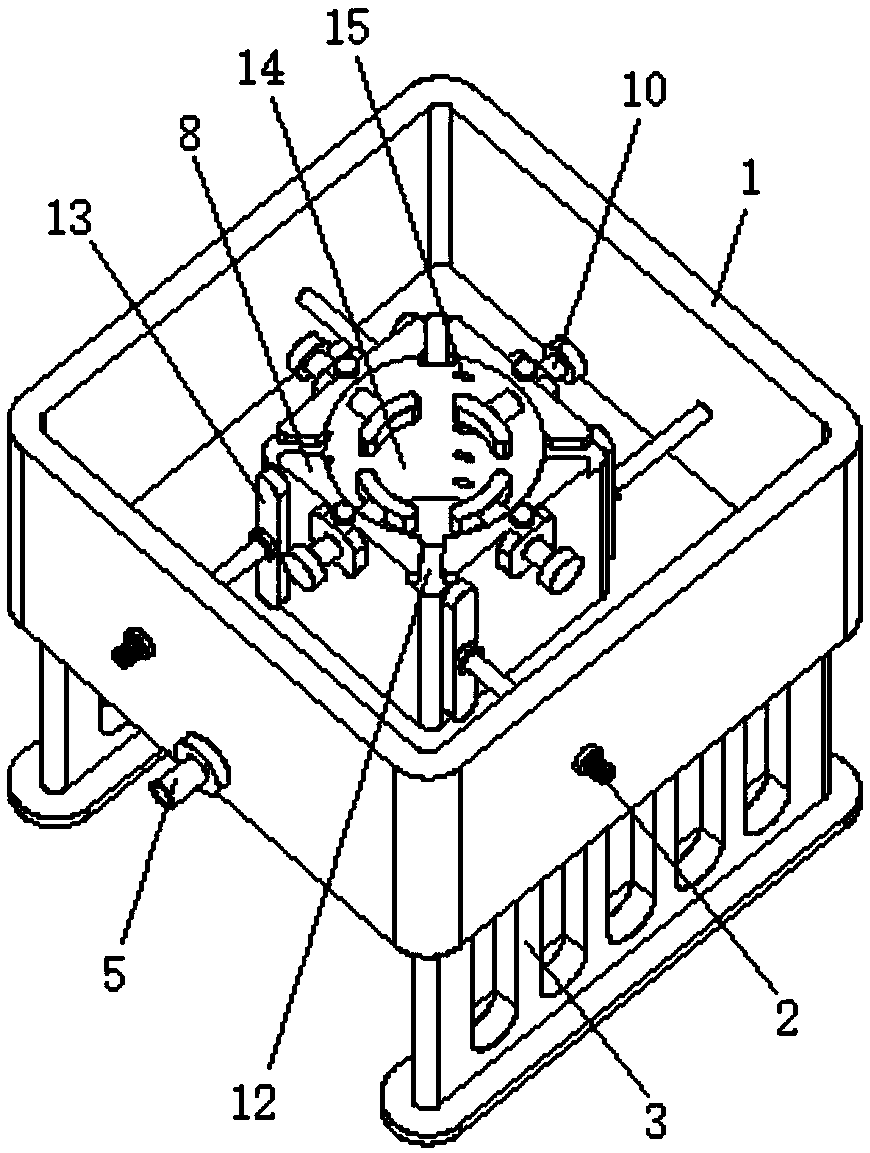
[0015] see Figure 1-2 , the present invention provides a technical solution: a cleaning and disinfection tank device for an endoscope room, comprising an outer cleaning tank body 1, and two sets of support plates 3 symmetrically distributed are arranged on the lower side of the outer cleaning tank body 1 for use in The outer cleaning tank 1 is supported and kept stable. The underside of the support plate 3 is provided with anti-skid pads 4 , the outer lower p...


PUM


Abstract

The invention discloses a cleaning and disinfection tank device for an endoscope room. The cleaning and disinfection tank device comprises an outer cleaning tank body, an inner cleaning tank body is arranged in the middle in the outer cleaning tank body, a cleaning column tank is arranged in the middle of the upper side of the inner cleaning tank body, and tangential cleaning holes evenly distributed at equal angles are formed in the side wall of the inner cleaning tank body, and a water distributing pipe is arranged on the side, close to the exteriors of the tangential cleaning holes, of theinner cleaning tank body; one end of a water inlet pipe is connected to the side, away from the inner cleaning tank body, of the water distributing pipe; and the other end of the water inlet pipe penetrates through the outer cleaning tank body and is connected with a water inlet connector. Through an arc-shaped limiting plate, the positions of medical apparatus and instruments to be cleaned and disinfected can be fixed during cleaning, adjusting is conducted conveniently according to the sizes of the medical apparatus and instruments through cooperation of fastening bolts and a sliding shaft,and the medical apparatus and instruments can be quickly cleaned through the tangential cleaning holes formed in the side wall of the inner cleaning tank body.

Description

technical field [0001] The invention relates to the technical field of medical instruments, in particular to a cleaning and disinfection tank device used in an endoscope room. Background technique [0002] An endoscope is a detection instrument that integrates traditional optics, ergonomics, precision machinery, modern electronics, mathematics, and software. It has image sensors, optical lenses, light source lighting, and mechanical devices. The internal channel of the endoscope is used for cleaning. The disinfection tank cleans and disinfects the medical instruments used. For example, the patent application publication number 201810162672.0 discloses a cleaning and disinfection tank device for endoscope room, including a device body, a protective rubber cover and a protective rubber tank. The device body The bottom is fixedly equipped with a load-bearing fixing groove, and the middle of the top of the bearing-fixing groove is fixedly installed with a cleaning fixing groove....

Claims


Application Information

Patent Timeline
IPC IPC(8): B08B3/02B08B13/00
CPCB08B3/02B08B13/00
Inventor 徐海艳惠良图
Owner 徐海艳
Features
  • R&D
  • Intellectual Property
  • Life Sciences
  • Materials
  • Tech Scout
  • Unparalleled Data Quality
  • Higher Quality Content
  • 60% Fewer Hallucinations
Learn More