Numerical control lathe power shaft center correcting device

A technology of CNC lathes and correction devices, applied in auxiliary devices, turning equipment, accessories of tool holders, etc., can solve the problems of inability to accurately correct the center of the power shaft, and achieve the effect of saving adjustment time and requiring guarantee

Pending Publication Date: 2019-03-01
上海阿为特精密机械股份有限公司
View PDF0 Cites 2 Cited by
  • Summary
  • Abstract
  • Description
  • Claims
  • Application Information

AI Technical Summary

Problems solved by technology

[0003] The technical problem to be solved by the present invention is to provide a center correction device for the power shaft of a CNC lathe in order to overcome the defect that the center of the power shaft cannot be accurately corrected in the prior art

Method used


Image

  • Numerical control lathe power shaft center correcting device
  • Numerical control lathe power shaft center correcting device

Examples


Embodiment Construction

[0030] The present invention is further illustrated below by means of examples, but the present invention is not limited thereto within the scope of examples.

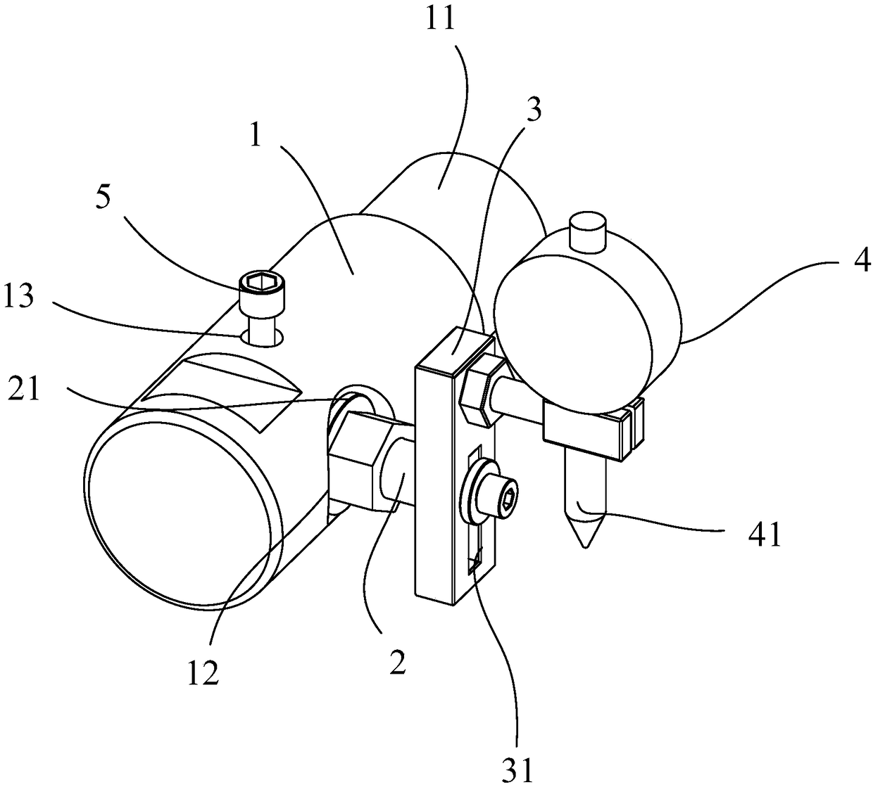
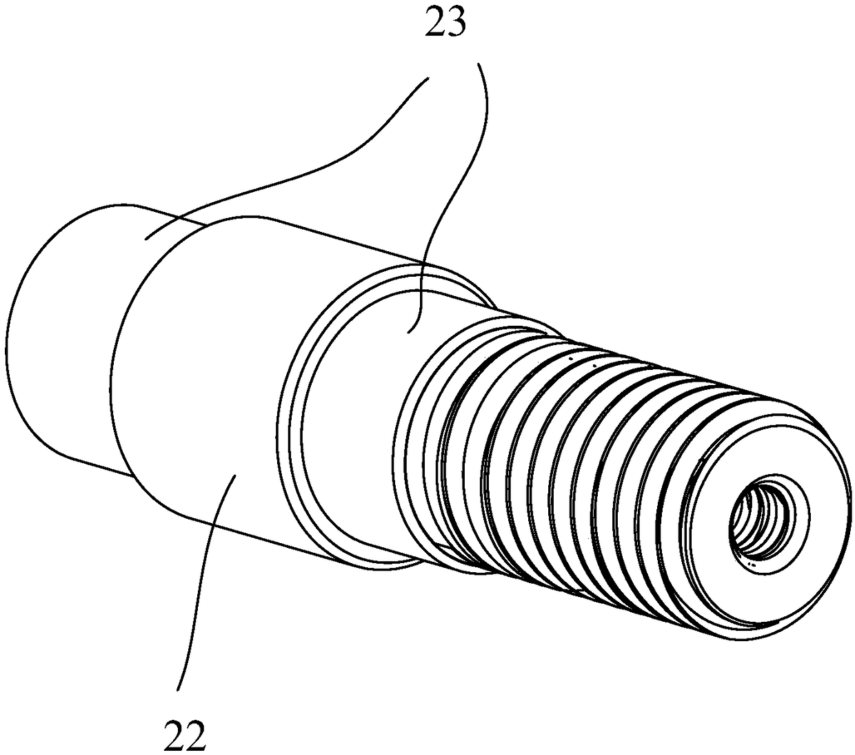
[0031] The power shaft center correction device of the numerically controlled lathe of this embodiment, such as figure 1 with figure 2 As shown, it includes: clamping spindle 1, connecting shaft 2, fixed frame 3 and dial indicator 4, clamping spindle 1 includes clamping part 11 and rotation hole 12, the axis of clamping part 11 and the axis of rotation hole 12 The axis is vertical and in the same plane, the connecting shaft 2 is installed in the rotating hole 12, the connecting shaft 2 can rotate in the rotating hole 12, the connecting shaft 2 is coaxial with the rotating hole 12, and the fixed frame 3 fixes the dial indicator 4 on the On the connecting shaft 2 , the dial indicator 4 has a gauge rod 41 , the dial gauge 4 can translate along the axis of the gauge rod 41 , and the axis of the gauge rod 41 is perpendicu...


PUM


Abstract

The invention discloses a numerical control lathe power shaft center correcting device. The numerical control lathe power shaft center correcting device comprises a clamping main shaft, a connecting shaft, a fixing frame and a dial indicator, wherein the clamping main shaft comprises a clamping part and a rotating hole, the axis of the clamping part and the axis of the rotating hole are perpendicular to each other and in the same plane, the connecting shaft is arranged in the rotating hole, the connecting shaft can rotate in the rotating hole, the connecting shaft and the rotating hole are coaxial, the fixing frame is used for fixing the dial indicator on the connecting shaft, the dial indicator is provided with a gauge rod, the dial indicator can be horizontally moved along the axis of the gauge rod, and the axis of the gauge rod and the axis of the connecting shaft are perpendicular to each other and in the same plane. According to the numerical control lathe power shaft center correcting device, a power shaft is directly verified through the dial indicator, the numerical control lathe power shaft center correcting device is convenient and fast, the center of a power tool is accurately adjusted, the machine adjusting time is saved, and the requirements of the product are guaranteed.

Description

technical field [0001] The invention relates to numerical control lathe equipment, in particular to a center correction device for a power shaft of a numerical control lathe. Background technique [0002] In machining, it is necessary to drill, tap and mill grooves on the axis of the workpiece, which requires the axis of the power shaft to pass through the axis of the workpiece. Traditional equipment can only adjust the center by naked eyes, and cannot accurately correct the center of the power shaft, which is inefficient and low in accuracy. Contents of the invention [0003] The technical problem to be solved by the present invention is to provide a center correction device for a power shaft of a numerically controlled lathe in order to overcome the defect that the center of the power shaft cannot be accurately corrected in the prior art. [0004] The present invention solves the above technical problems through the following technical solutions: [0005] A center corr...

Claims


Application Information

Patent Timeline
Patent Type & Authority Applications(China)
IPC IPC(8): B23B25/06
CPCB23B25/06
Inventor 牛卫祥汪彬慧熊朝林高福喜
Owner 上海阿为特精密机械股份有限公司
Why Eureka
Try Eureka