
Fully-automatic chamfering machine for LC ceramic ferrules

A ceramic ferrule and fully automatic technology, which is applied to machine tools, grinding machines, metal processing equipment, etc., which are suitable for grinding the edge of workpieces, can solve the problems of wasting working hours, affecting production efficiency, increasing operating procedures, etc., so as to improve production efficiency and the effect of precision

Pending Publication Date: 2019-03-01
GAOAN TIANFU OPTOELECTRONICS TECH
View PDF0 Cites 0 Cited by
  • Summary
  • Abstract
  • Description
  • Claims
  • Application Information

AI Technical Summary

Problems solved by technology

[0002] At present, the LC ceramic ferrule needs to be cut and chamfered during the production process. The traditional processing method is to transport the material to the chamfering equipment after the cutting is completed, and then process it separately. In this way, it is necessary to increase the processing equipment and expand the plant area. , At the same time, it will increase the operating procedures, waste man-hours and procedures, and affect the entire production efficiency

Method used


Image

  • Fully-automatic chamfering machine for LC ceramic ferrules
  • Fully-automatic chamfering machine for LC ceramic ferrules
  • Fully-automatic chamfering machine for LC ceramic ferrules

Examples


Embodiment Construction

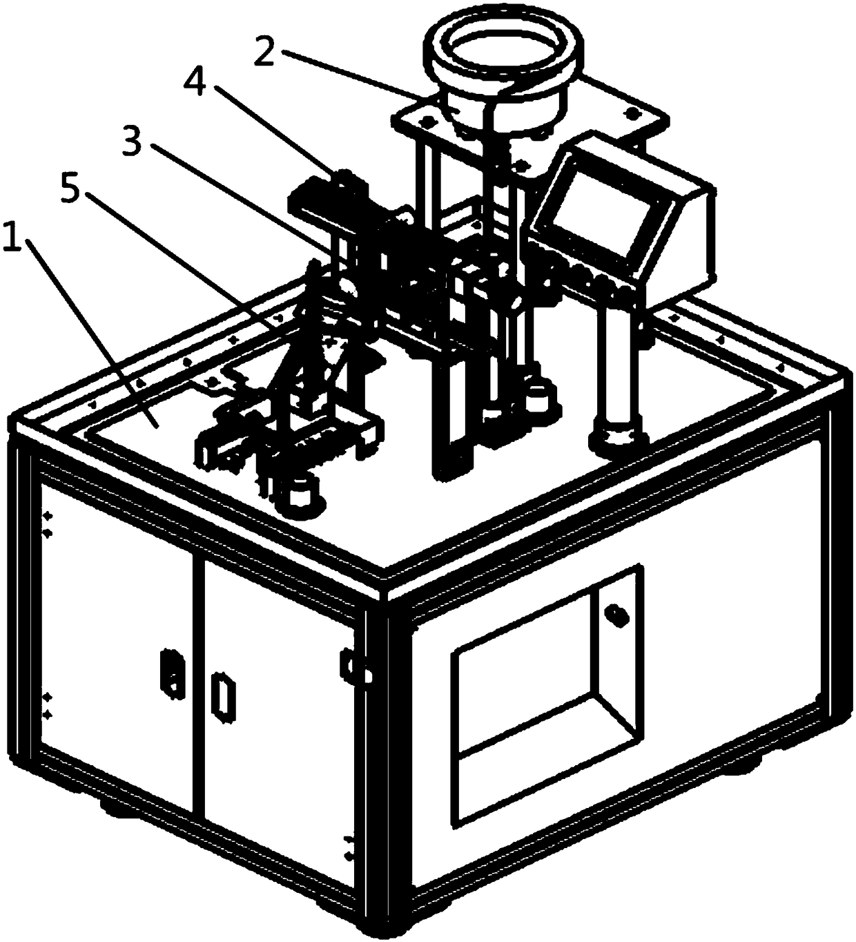
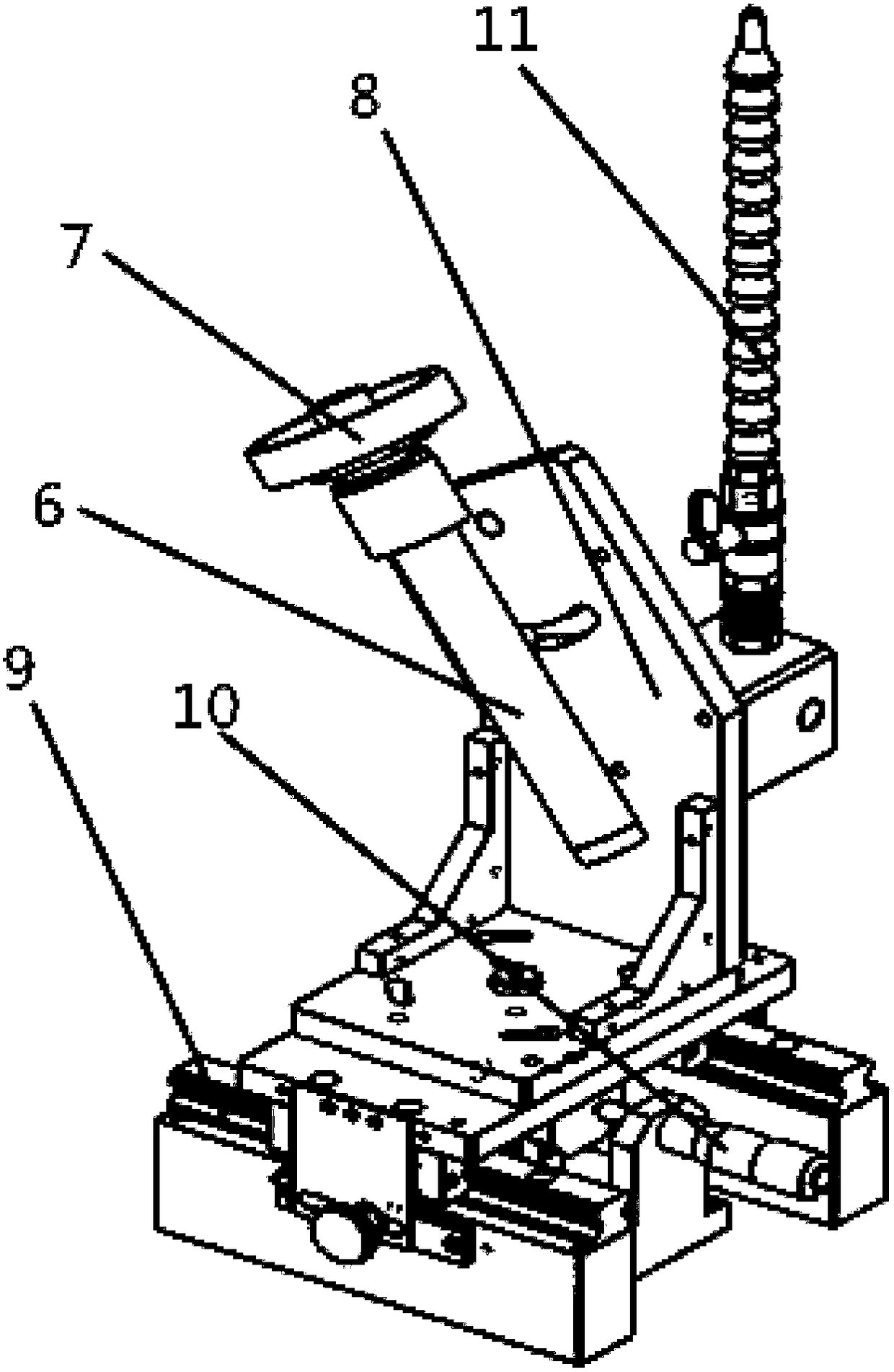
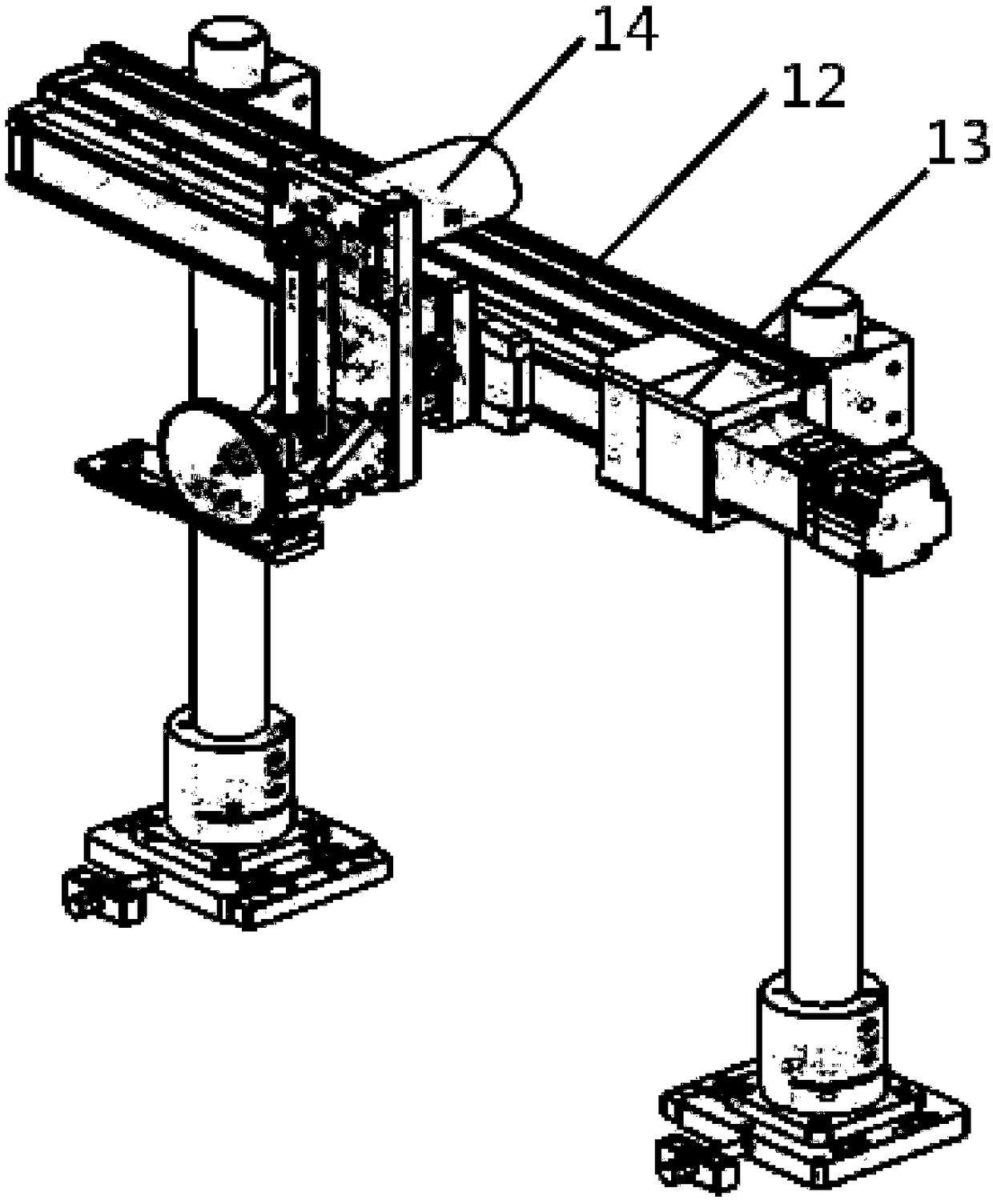
[0020] As shown in the figure, a fully automatic chamfering machine for LC ceramic ferrules includes a frame 1, an automatic feeding mechanism 2, a material cutting mechanism 3, a conveying mechanism 4 and a chamfering mechanism 5; the automatic feeding mechanism 2 Located on the frame 1, fixedly connected with the frame 1; the conveying mechanism 4 is located on the frame 1, located on the side of the automatic feeding mechanism 2, connected to the The automatic feeding mechanism 2; the material cutting mechanism 3 is located on one side of the conveying mechanism 4, corresponding to the conveying mechanism 4, and fixed on the frame 1 at the same time; the inverted The corner mechanism 5 is located on one side of the material cutting mechanism 3, corresponding to the material cutting mechanism 3, and corresponding to the conveying mechanism 4;

[0021] The chamfering mechanism 5 includes a pneumatic main shaft 6, a chamfering grinding wheel 7, a chamfering base 8, a linear sl...


PUM


Abstract

The invention provides a fully-automatic chamfering machine for LC ceramic ferrules. The fully-automatic chamfering machine for LC ceramic ferrules comprises a machine frame, an automatic feeding mechanism, a cutting mechanism, a conveying mechanism and a chamfering mechanism, wherein the automatic feeding mechanism is located on the machine frame and fixedly connected with the machine frame; theconveying mechanism is located on the machine frame and connected with the automatic feeding mechanism; the cutting mechanism is located on one side of the conveying mechanism and corresponds to the conveying mechanism; and the chamfering mechanism is located on one side of the cutting mechanism and corresponds to the cutting mechanism. According to the fully-automatic chamfering machine for LC ceramic ferrules, materials are fed in a vibrating mode through a vibration plate, a cutting cylinder moves to cut off the materials, a linear motor drives the materials to move to one side of a rotarymotor, the rotary motor drives the materials to rotate, at the same time, a pneumatic spindle is started and drives a chamfering abrasive wheel to rotate to chamfer the materials, and a micrometer head can adjust the position of a chamfering base and rotate the chamfering base, so that the relative position of the chamfering abrasive wheel and the materials is changed, the chamfering size is adjusted, and the production efficiency and precision are improved.

Description

technical field [0001] The invention relates to a fully automatic chamfering machine for LC ceramic ferrule. Background technique [0002] At present, the LC ceramic ferrule needs to be cut and chamfered during the production process. The traditional processing method is to transport the material to the chamfering equipment after the cutting is completed, and then process it separately. In this way, it is necessary to increase the processing equipment and expand the plant area. , At the same time, it will increase the operating procedures, waste man-hours and procedures, and affect the entire production efficiency. Contents of the invention [0003] The technical problem to be solved by the present invention is to provide a fully automatic chamfering machine for LC ceramic ferrules, which combines material feeding and processing, improves production efficiency, saves production space, and improves the automation of the company's production. [0004] In order to solve the ...

Claims


Application Information

Patent Timeline
Patent Type & Authority Applications(China)
IPC IPC(8): B24B9/06
CPCB24B9/06
Inventor 邹支农
Owner GAOAN TIANFU OPTOELECTRONICS TECH
Learn More