A chamfering jig and installation structure for a surface grinder

A surface grinding machine and installation structure technology, which is applied in the direction of grinding machines, parts of grinding machine tools, and machine tools suitable for grinding the edge of workpieces, etc., can solve the problems of not being able to freely grind chamfering and chamfering fixtures, and achieve structural Simple, simple structure and installation structure, easy maintenance effect

Active Publication Date: 2021-03-30
JIAXING UNIV
View PDF6 Cites 2 Cited by
  • Summary
  • Abstract
  • Description
  • Claims
  • Application Information

AI Technical Summary

Problems solved by technology

The existing chamfering fixtures all support the formwork through positioning inclined surfaces, and there is a certain distance between the positioning inclined surfaces, which is enough to make the sharp edges and corners of the template to be polished be placed between the positioning inclined surfaces, and the positioning inclined surfaces are fixed by the positioning block. The middle chamfering jig is set according to different templates to be polished, because different chamfers need to be ground, and the existing chamfering jigs are not adjustable, and chamfers of different sizes cannot be freely ground

Method used


Image

  • A chamfering jig and installation structure for a surface grinder
  • A chamfering jig and installation structure for a surface grinder
  • A chamfering jig and installation structure for a surface grinder

Examples


Embodiment 1

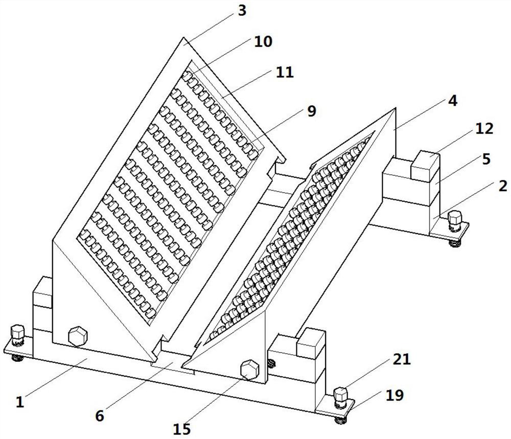
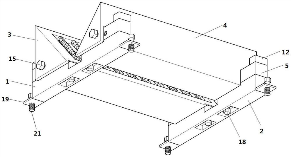
[0031] Such as Figure 1-Figure 4 As shown, a chamfering jig for a surface grinder includes a first positioning block 1, a second positioning block 2, a first positioning bevel 3 and a second positioning bevel 4, on the first positioning block 1 and the second positioning block 2 The left and right ends are all fixedly provided with fixed block 5, and all are provided with limit projection 12 at the end side of each fixed block 5 upper ends, and limit projection 12 can make the positioning inclined-plane can not come off when adjusting the position on the positioning block, the first Positioning block 1, the upper end of the middle part of the second positioning block 2 are provided with a square groove 6, the slopes of the first positioning slope 3 and the second positioning slope 4 are perpendicular to each other, and the rectangular object to be polished is placed on the first positioning slope 3 and the second positioning slope 4. Between the slopes of the positioning slop...

Embodiment 2

[0035] Such as Figure 1-Figure 4 As shown, a chamfering jig for a surface grinder includes a first positioning block 1, a second positioning block 2, a first positioning bevel 3 and a second positioning bevel 4, on the first positioning block 1 and the second positioning block 2 The left and right ends are all fixedly provided with fixed block 5, and all are provided with limit projection 12 at the end side of each fixed block 5 upper ends, and limit projection 12 can make the positioning inclined-plane can not come off when adjusting the position on the positioning block, the first Positioning block 1, the upper end of the middle part of the second positioning block 2 are provided with a square groove 6, the slopes of the first positioning slope 3 and the second positioning slope 4 are perpendicular to each other, and the rectangular object to be polished is placed on the first positioning slope 3 and the second positioning slope 4. Between the slopes of the positioning slop...

Embodiment 3

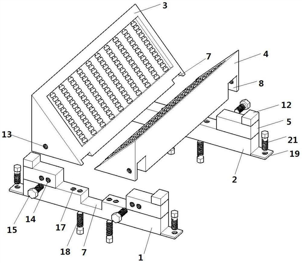
[0040] A chamfering jig for a surface grinder includes a first positioning block 1 , a second positioning block 2 , a first positioning slope 3 and a second positioning slope 4 .

[0041] Different from Embodiment 1 and Embodiment 2, the left and right ends of the first positioning block 1 and the second positioning block 2 are not provided with fixed blocks 5, and the slopes of the first positioning slope 3 and the second positioning slope 4 are perpendicular to each other. , the rectangular object to be polished is placed between the slopes of the first positioning bevel 3 and the second positioning bevel 4, the included angle of 90° is just the same as the grinding corner of the rectangular object to be polished, the first positioning bevel 3, the second The slope angle of the positioning slope 4 can also be other angles, which can be set according to the object to be polished. Grooves corresponding to the first positioning block 1 are provided on the bottoms of the first p...


PUM


Abstract

The invention relates to the technical field of chamfering production equipment, in particular to a chamfering jig for a surface grinding machine and a mounting structure. The chamfering jig comprisesa first positioning block, a second positioning block, a first positioning inclined surface and a second positioning inclined surface, wherein fixing blocks are fixedly arranged at the left end and the right end of the first positioning block and the left end and the right end of the second positioning block separately, square grooves are formed in the upper end of the middle of the first positioning block and the upper end of the middle of the second positioning block separately, first L-shaped grooves corresponding to the fixing blocks and the first positioning block are formed in the bottom of the first positioning inclined surface, and second L-shaped grooves corresponding to the fixing blocks and the second positioning block are formed in the bottom of the second positioning inclinedsurface; and the mounting structure comprises a first positioning screw hole A, a first positioning screw hole B, a first fixing bolt, a second positioning screw hole A, a second positioning screw hole B and a second fixing bolt. According to the chamfering jig, the distance between the positioning inclined surfaces can be freely adjusted, so that the chamfering size of a to-be-ground object is adjusted, the to-be-ground object slides along the positioning inclined surfaces for grinding, and the working efficiency is improved.

Description

technical field [0001] The invention relates to the technical field of chamfering production equipment, in particular to a chamfering jig and installation structure for a surface grinder. Background technique [0002] Chamfering is to remove the burrs produced by machining on the parts. In order to facilitate the assembly of parts, chamfering is generally made at the end of the parts. The edges and corners of the existing mold templates are mostly sharp. For the safety of use, the chamfering fixture will be used The edges and corners of the formwork are polished, and the original sharp edges and corners are polished into smooth radians, which not only has a smooth and beautiful effect, but also improves safety. The existing chamfering fixtures all support the formwork through positioning inclined surfaces, and there is a certain distance between the positioning inclined surfaces, which is enough to make the sharp edges and corners of the template to be polished be placed bet...

Claims


Application Information

Patent Timeline
Patent Type & Authority Patents(China)
IPC IPC(8): B24B9/00B24B41/06B24B41/00F16B1/02
CPCB24B9/00B24B41/00B24B41/06F16B1/02
Inventor 赵浩李洪武马如远丁立军周丽王成贤戴婷王挺习聪玲陈晟王璇王殿梁
Owner JIAXING UNIV
Why Eureka
Try Eureka