
Tree trunk skin removing machine and skin removing method

A peeling machine and tree trunk technology, which is applied in bark, wood processing equipment, manufacturing tools, etc., can solve the problems of low peeling efficiency, reduced processing efficiency, and high energy consumption, and achieves manpower saving, complete functions, and automation high effect

Active Publication Date: 2019-03-01
张小汴 +1
View PDF8 Cites 14 Cited by
  • Summary
  • Abstract
  • Description
  • Claims
  • Application Information

AI Technical Summary

Problems solved by technology

[0003] Before using wood to make furniture, it usually needs to go through logging, cutting, peeling, and cutting to obtain wood. When peeling the cut trunk, it usually uses manual peeling. Manual peeling consumes a lot of energy and the peeling efficiency is low. , which reduces the processing efficiency; when mechanical peeling is used, a single wood feed needs to be manually transported repeatedly, which leads to low feed continuity, increases the idling time of the equipment, increases the energy consumption of the equipment, and the current peeling equipment cannot Carry out the pulverization of bark, still lack a kind of device that can pulverize bark after the trunk is peeled

Method used


Image

  • Tree trunk skin removing machine and skin removing method
  • Tree trunk skin removing machine and skin removing method
  • Tree trunk skin removing machine and skin removing method

Examples


Embodiment Construction

[0034] A specific embodiment of the present invention will be described in detail below in conjunction with the accompanying drawings, but it should be understood that the protection scope of the present invention is not limited by the specific embodiment.

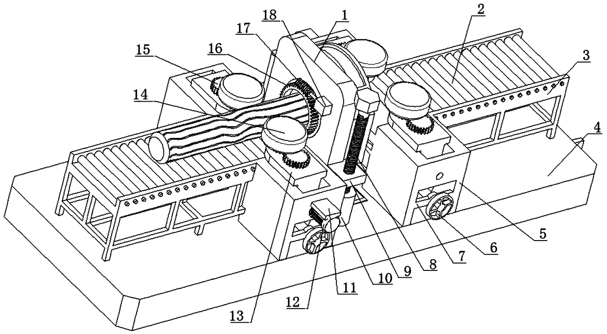
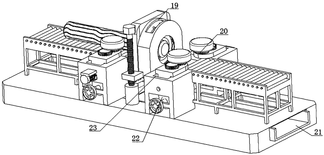
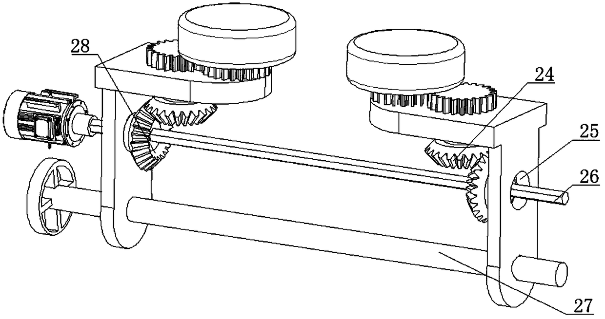
[0035] Such as Figure 1-Figure 11As shown, the present invention includes a bottom plate 4, a guide post 43 is fixed on one side of the upper middle part of the bottom plate 4, and a cylindrical block 10 is fixed on the other side, and the upper side of the cylindrical block 10 is hinged to the lower end of the lead screw 8, so The lead screw 8 is threadedly connected to one end of the horizontal plate 9, one side of the horizontal plate 9 is fixedly connected to the lower side of the vertical plate 1, the center of the vertical plate 1 is provided with a central hole, and the other side of the vertical plate 1 Another horizontal plate 9 is fixedly connected, and the other horizontal plate 9 is passed through by the guide...


PUM


Abstract

The invention discloses a tree trunk skin removing machine and a skin removing method, relates to the field of tree trunk skin removing equipment, in particular to the tree trunk skin removing machine. The tree trunk skin removing machine comprises a T-shaped bottom plate. The tree trunk skin removing machine is characterized in that a supporting shaft is fixed to one end of the upper side of theT-shaped bottom plate, the upper side of the supporting shaft is hinged to one end of a U-shaped rod, and a first top block is in threaded connection with the other end of the U-shaped rod. The two opposite ends of the upper side of the T-shaped bottom plate are separately and fixedly connected with two ends of a cross rod of a T-shaped groove rod through an L-shaped bracket, a T-shaped sliding rail is arranged on the cross rod of the T-shaped groove rod, a first T-shaped sliding block is arranged in the T-shaped sliding rail, a first cylinder rod is fixed to the middle of one side of the first T-shaped sliding block, and the first cylinder rod penetrates through the T-shaped sliding rail, a first sliding groove at the lower end of a straight groove rod and a clamping groove at the upper end of an H-shaped groove rod. The tree trunk skin removing machine can realize the skin removing of tree trunks and smashing of tree skins.

Description

technical field [0001] The invention relates to the field of tree trunk peeling equipment, in particular to a tree trunk peeling machine and a peeling method. Background technique [0002] Wood has the functions of light material, corrosion resistance, beautiful appearance, green environmental protection, etc. It is widely used in making furniture, decoration materials and decorations. Wood has become one of the most popular materials in people's life. [0003] Before using wood to make furniture, it usually needs to go through logging, cutting, peeling, and cutting to obtain wood. When peeling the cut trunk, it usually uses manual peeling. Manual peeling consumes a lot of energy and the peeling efficiency is low. , which reduces the processing efficiency; when mechanical peeling is used, a single wood feed needs to be manually transported repeatedly, which leads to low feed continuity, increases the idling time of the equipment, increases the energy consumption of the equip...

Claims


Application Information

Patent Timeline
Patent Type & Authority Applications(China)
IPC IPC(8): B27L1/08B27L11/00
CPCB27L1/08B27L11/00B27L11/005
Inventor 蔡奕凡
Owner 张小汴
Learn More