

Adjustable printing device
A printing device and an adjustable technology, which is applied to printing devices, printing, typewriters, etc., can solve problems such as failure to meet protection requirements, affect printing quality, increase the distance between the printing working end and the surface to be printed, and achieve a wide range of applications and improve Print quality, the effect of avoiding contact with occluders
- Summary
- Abstract
- Description
- Claims
- Application Information
AI Technical Summary
Problems solved by technology
Method used
Image

Examples
no. 1 example
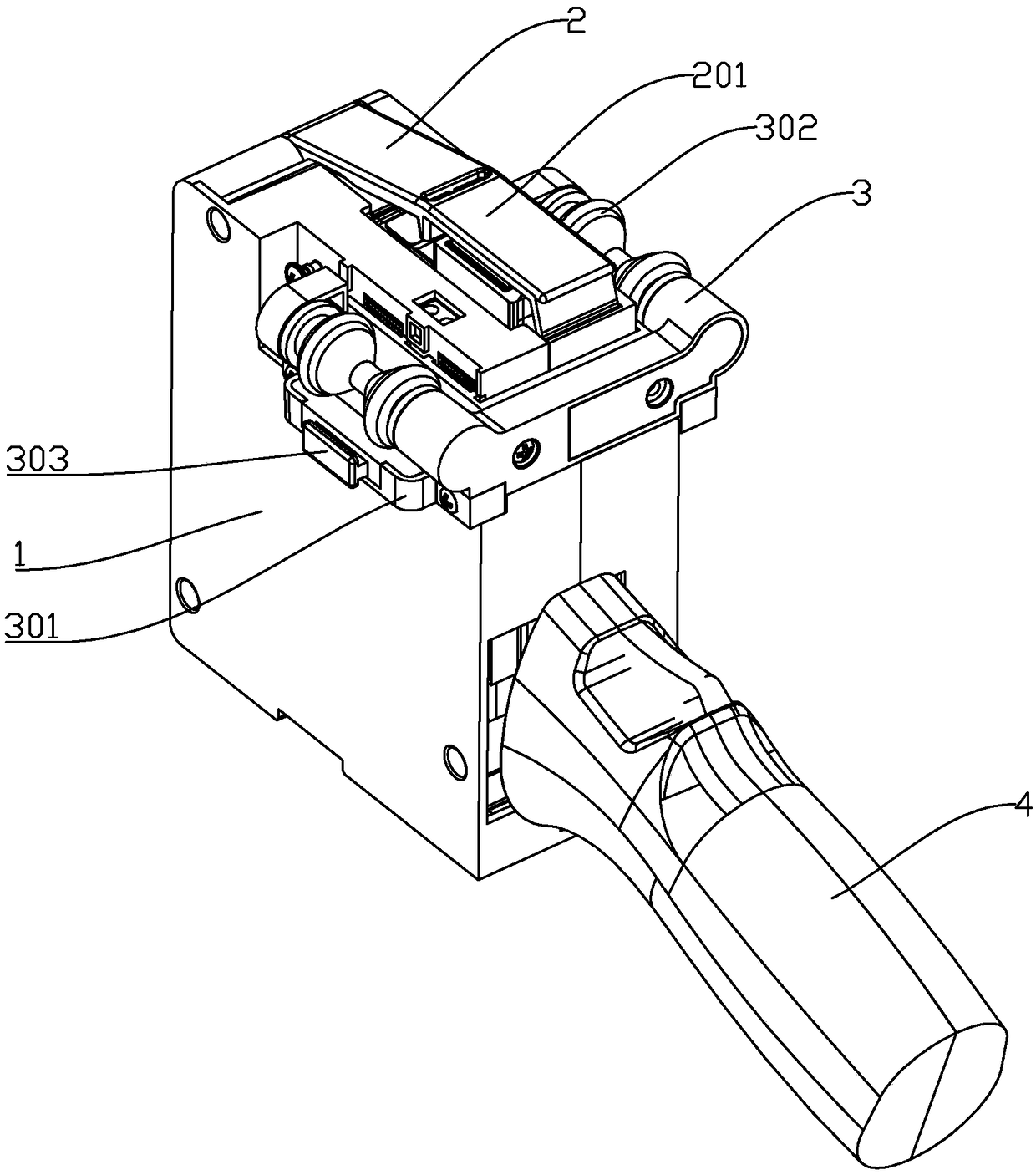
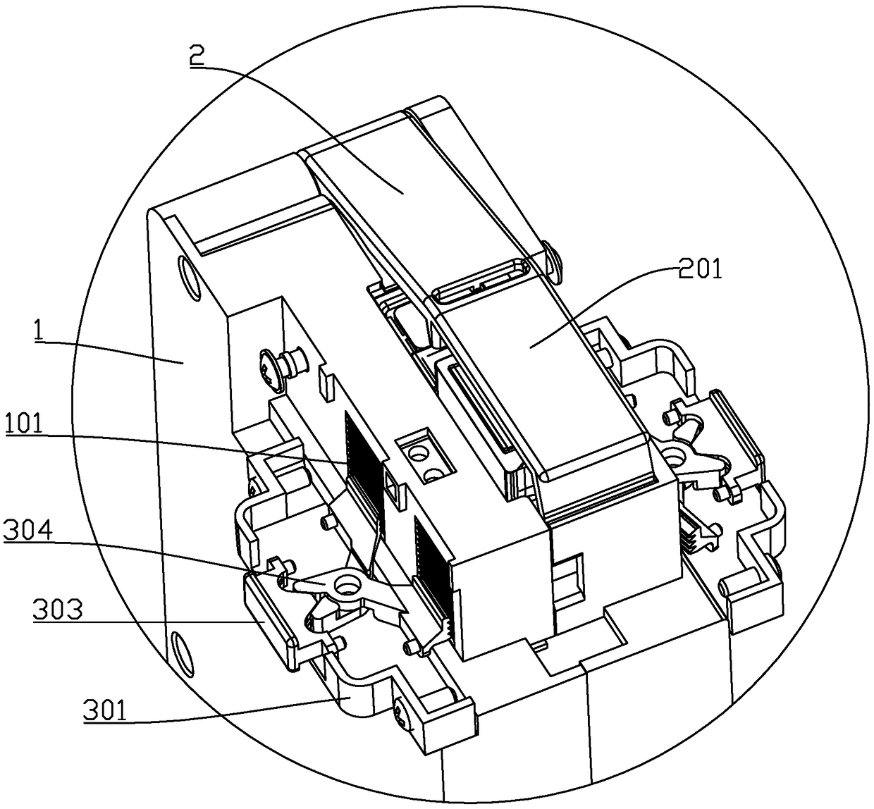
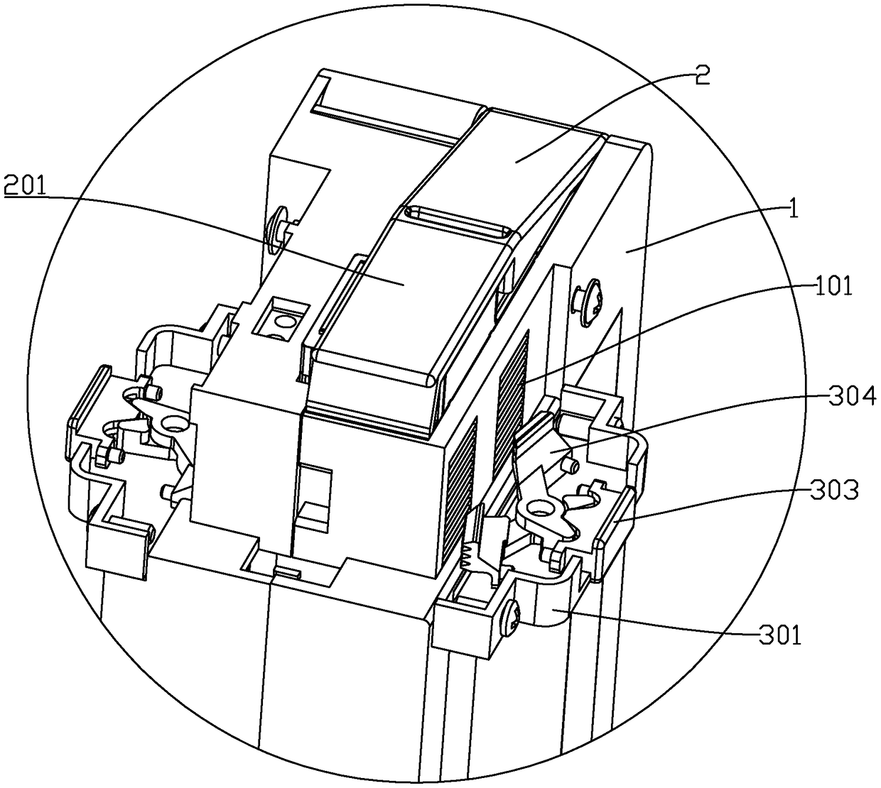
[0039] refer to Figure 1 to Figure 11 , the present invention discloses an adjustable printing device, which includes a main body 1, a control circuit board and an ink cartridge 9 for storing ink are arranged inside the main body 1, and a printing device electrically connected to the control circuit board is arranged at the lower end of the main body 1. The nozzle 904, the ink cartridge 9 is provided with an ink outlet corresponding to the print nozzle 904, and the body 1 is symmetrically provided with a roller assembly 3 on both sides of the print nozzle 904, and the roller assembly 3 is installed on the body 1 through an adjustment mechanism and can be The installation height is adjusted by the adjustment mechanism, thereby realizing the adjustment of the distance from the working surface of the printing nozzle 904 .
[0040] In order to ensure that the heights of the roller assemblies 3 on both sides are consistent, a linkage structure is fixed outside the body 1 between t...
no. 2 example
[0083] This embodiment takes the first embodiment as the main body, and the main difference is that the adjustment mechanism in this embodiment replaces the adjustment rack 101 with a plurality of positioning holes arranged vertically, and correspondingly, the locking The mechanism is equipped with a positioning column that matches the positioning hole, so as to realize the lifting and locking of the roller assembly.
PUM
 Abstract
Description
Claims
Application Information