A road guardrail with flood protection and isolation function
A road and guardrail technology, applied in dikes, roads, roads, etc., can solve the problems of water accumulation, limited drainage capacity, insufficient functions, etc., and achieves installation speed, lightness, simple structure, and enhanced functionality Effect
- Summary
- Abstract
- Description
- Claims
- Application Information
AI Technical Summary
Problems solved by technology
Method used
Image
Examples
Embodiment 1
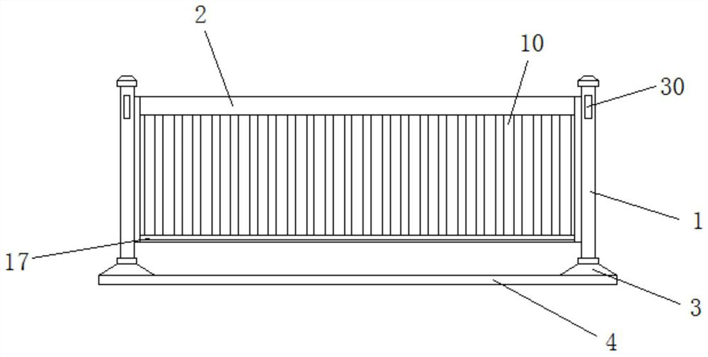
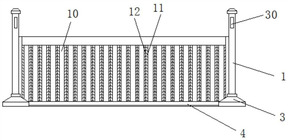
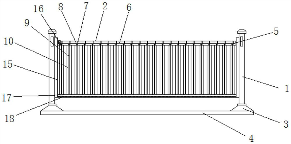
[0024] Embodiment 1: as Figure 1-9 As shown, a road guardrail with flood prevention and isolation function includes a column 1, a sliding frame 15, a beam 2 and a supporting bottom beam 17, the column 1 is provided with two groups, and the side wall of the column 1 is fixedly connected with a fluorescent strip 30. The bottom of the column 1 is fixedly connected with a foot 3, and the side wall of the column 1 and the foot 3 is provided with an adjustment groove 21, and the upper side of the adjustment groove 21 is provided with a positioning groove 22, and the carriage 15 is located at The adjustment groove 21 is flexibly connected, and the crossbeam 2 is positioned at the top between two groups of carriages 15. Both sides of the top of the crossbeam 2 are provided with chute 19, and the chute 19 is movably connected with a connecting bolt 24. The top of the connecting bolt 24 is fixedly connected with a plug-in board 20, the top of the plug-in board 20 is fixedly connected w...
Embodiment 2
[0025] Embodiment 2: as Figure 1-10 As shown, a road guardrail with flood prevention and isolation function includes a column 1, a sliding frame 15, a beam 2 and a supporting bottom beam 17, the column 1 is provided with two groups, and the side wall of the column 1 is fixedly connected with a fluorescent strip 30. The bottom of the column 1 is fixedly connected with a foot 3, and the side wall of the column 1 and the foot 3 is provided with an adjustment groove 21, and the upper side of the adjustment groove 21 is provided with a positioning groove 22, and the carriage 15 is located at The adjustment groove 21 is flexibly connected, and the crossbeam 2 is positioned at the top between two groups of carriages 15. Both sides of the top of the crossbeam 2 are provided with chute 19, and the chute 19 is movably connected with a connecting bolt 24. The top of the connecting bolt 24 is fixedly connected with a plug-in board 20, the top of the plug-in board 20 is fixedly connected ...
PUM
 Abstract
Description
Claims
Application Information
 - R&D
- Intellectual Property
- Life Sciences
- Materials
- Tech Scout
- Unparalleled Data Quality
- Higher Quality Content
- 60% Fewer Hallucinations
Browse by: Latest US Patents, China's latest patents, Technical Efficacy Thesaurus, Application Domain, Technology Topic, Popular Technical Reports.
© 2025 PatSnap. All rights reserved.Legal|Privacy policy|Modern Slavery Act Transparency Statement|Sitemap|About US| Contact US: help@patsnap.com


