Elbow sealing performance test device

A test device and sealing technology, which is applied in the direction of fluid tightness testing, measuring devices, liquid tightness measurement using liquid/vacuum degree, etc., can solve the problem that the test results cannot be effectively guaranteed, the detection efficiency is low, and the operation process is easy Deviations and other problems occur, to achieve the effect of accurate and reliable test results and convenient operation

Active Publication Date: 2019-03-01
山东盛祥动力有限责任公司
View PDF10 Cites 3 Cited by
  • Summary
  • Abstract
  • Description
  • Claims
  • Application Information

AI Technical Summary

Problems solved by technology

[0002] In the prior art, manual detection is mostly used when performing the elbow tightness test, and the operation is repeated, and the detection efficiency is low. Moreover, due to

Method used


Image

  • Elbow sealing performance test device
  • Elbow sealing performance test device
  • Elbow sealing performance test device

Examples


Example Embodiment

[0021] Example one:

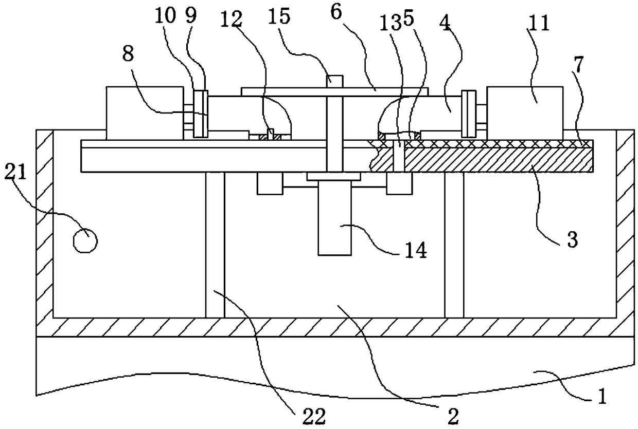
[0022] Such as figure 1 with figure 2 As shown, an elbow tightness test device includes a frame 1, a water tank 2 is provided on the frame 1, a lifting plate 3 is provided in the water tank 2, the frame 1 and the lifting plate 3 A lifting drive mechanism is provided in between, and the lifting drive mechanism includes a guide post 22 fixedly installed on the lower surface of the lifting plate, and a guide sleeve cooperating with the guide post is provided on the frame, and the guide post is connected There is a piston rod of a lifting plate driving the cylinder, the lifting plate 3 is provided with a elbow clamping position, and the lifting plate is provided with a elbow clamp for fixing the elbow at the elbow clamping position. The lifting plate 3 is also provided with a blocking device for blocking the two ports of the elbow, and the lifting plate 3 is also provided with an air inlet device communicating with one port of the elbow 4 clamped by the elbow c...

Example Embodiment

[0029] Embodiment two:

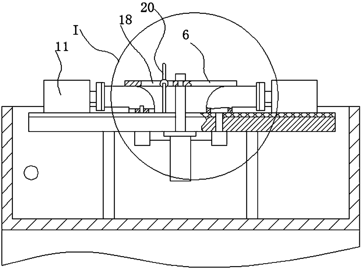
[0030] The structure of the second embodiment is basically the same as that of the first embodiment, the difference is that, as image 3 with Figure 4 As shown, the pressing down driving mechanism further includes an annular groove 16 provided on the upper part of the lifting column, the lower pressing plate is provided with a through hole, and the through hole is rotatably installed in the annular groove 16, and The first end of the lower pressing plate is pressed on the elbow 4, the lifting plate is provided with a guide column 17 which extends obliquely upward, and the lower pressing plate is provided along the length of the lower pressing plate. The cross section of the two groove walls in the width direction of the guide groove 18 is arc 19, and the movable ball 20 is movably installed in the guide groove 18, and the spherical surface of the movable ball 20 is attached to the On the groove wall in the width direction of the guide groove 18, a guide ...


PUM


Abstract

The invention discloses an elbow sealing performance test device, which comprises a rack. A water tank is arranged on the rack; the water tank is internally provided with a lifting plate; a lifting driving mechanism is arranged between the rack and the lifting plate; an elbow clamping position is arranged on the lifting plate; the lifting plate is provided with an elbow clamp for fixing the elbowon the elbow clamping position; the lifting plate is also provided with a sealing device for sealing the two ports of the elbow; the lifting plate is also provided with an air inlet device communicated with one port of the elbow clamped by the elbow clamp; the water tank is also connected with a water injection device; the lifting plate rises, the elbow is fixed on the lifting plate through the elbow clamp, the sealing device seals the two ports of the elbow, and later, the lifting plate falls to enable the elbow to be immersed in water in the water tank, and then, the air inlet device provides air for one port of the elbow, whether bubbles appear in the water tank is observed, the sealing performance of the elbow is judged, the operation is convenient, the test result is accurate and reliable, and the sealing performance of the elbow can be tested effectively.

Description

technical field [0001] The invention relates to an elbow tightness test device. Background technique [0002] In the prior art, manual detection is mostly used when performing the elbow tightness test, and the operation is repeated, and the detection efficiency is low. Moreover, due to the complete reliance on manual operation, deviations are prone to occur during the operation, and the test results cannot be effectively guaranteed. , and requires a lot of manpower. Contents of the invention [0003] In order to make up for the above deficiencies, the present invention provides an elbow airtightness test device which can effectively improve the efficiency of the elbow airtightness test and ensure the accuracy of the test results. [0004] The technical solution of the present invention is: a bend pipe tightness test device, including a frame, a water tank is arranged on the frame, a lifting plate is arranged in the water tank, and a lifting plate is arranged between the f...

Claims


Application Information

Patent Timeline
IPC IPC(8): G01M3/08
CPCG01M3/083
Inventor 杨培友张学义马炳强杜泽通田立明李建张淑燕任华李烽炬
Owner 山东盛祥动力有限责任公司
Why Eureka
Try Eureka