Traction mechanism

A technology of racks and traction parts, applied in the direction of overhead lines/cable equipment, etc., can solve problems such as complex structures

Pending Publication Date: 2019-03-01
尚廷东
View PDF1 Cites 0 Cited by
  • Summary
  • Abstract
  • Description
  • Claims
  • Application Information

AI Technical Summary

Problems solved by technology

[0005] The purpose of the present invention is to provide a stretching mechanism to solve the problem that the stretching mechanism in the prior art needs to be equipped with multiple friction winding wheels, resulting in a complex structure

Method used


Image

  • Traction mechanism

Examples


Embodiment Construction

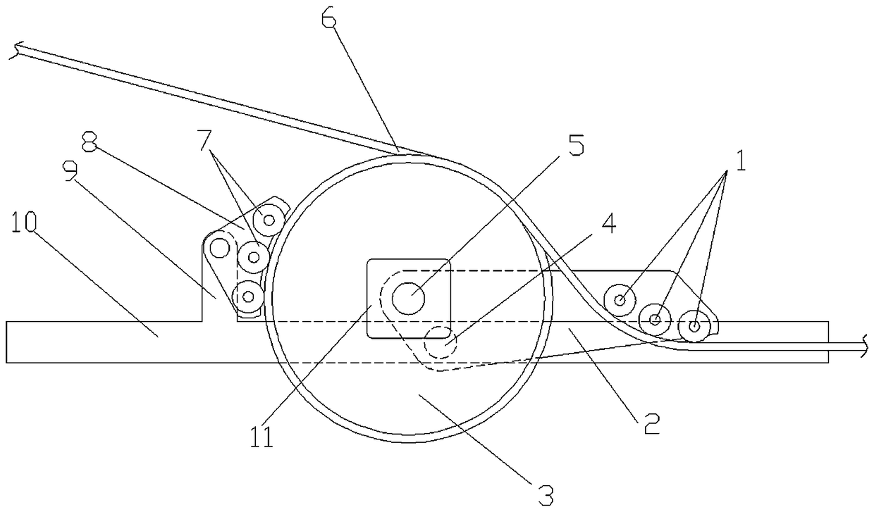
[0016] An example of a stretch mechanism figure 1 Shown: the frame 10 is included. In this embodiment, the frame is a beam structure with a length extending in the left and right direction. The frame is rotatably equipped with a rocker arm 2 with a rotation axis extending in the front and rear direction. Item 4 in the figure represents the rocker arm 2 Rotating shaft, the rocker arm is rotatably equipped with a winding pressure roller 3 for winding in one end of the corresponding traction member 6 and winding out at the other end. Item 5 in the figure represents the rotation shaft of the winding pressure roller 3, and the rotation axis of the winding pressure wheel The rotation axis of the arm is arranged in parallel, and the rotation axis of the winding pressure wheel is on the left side of the rotation axis of the rocker arm. In this embodiment, the winding pressure wheel is provided with a winding wheel groove, and the radius of the winding pressure wheel is four times the d...


PUM


Abstract

The invention relates to a traction mechanism. The traction mechanism comprises a machine frame, wherein a rocker arm is rotationally assembled on the machine frame; a wire winding pressing wheel usedfor allowing one end of a corresponding traction part to be wound in and the other end to be wound out is rotationally assembled on the rocker arm; the rotating axis of the wire winding pressing wheel is parallel to that of the rocker arm; a pressing wheel driving mechanism for driving the wire winding pressing wheel to rotate is installed on the rocker arm; and a wire pressing rolling body matched with the wire winding pressing wheel to apply pressure to the traction part is arranged, beside the wire winding pressing wheel, on the machine frame. According to the traction mechanism, the problem that the structure is complex due to the fact that a plurality of friction winding wheels need to be arranged in a traction mechanism in the prior art is solved.

Description

Technical field [0001] The invention relates to a stretch mechanism in the field of electric wiring. Background technique [0002] In the field of power wiring, it is often encountered that a stretch mechanism is used to pull flexible traction parts such as cables or ropes for the purpose of paying off, lifting or maintaining the tension of the flexible parts. [0003] An existing stretch mechanism such as "a tractor for aerial operations" disclosed in Chinese Patent CN106684760A, the tractor includes a frame on which a traction mechanism and a drive mechanism are arranged, and the traction mechanism is used for friction winding traction Parts, including at least one active friction winding wheel and at least one driven friction winding wheel. The active friction winding wheel and the driven friction winding wheel are respectively rotatably arranged on the frame. The active friction winding wheel and the driven friction winding wheel lead to the traction member in turn The power o...

Claims


Application Information

Patent Timeline
IPC IPC(8): H02G1/04
CPCH02G1/04
Inventor 郭沛张红涛原玮刘建锋梅志强陶春蓉吴建岭刘克伟尚廷东李赏郑楷文
Owner 尚廷东
Why Eureka
Try Eureka