Blade-replaceable saw

A blade-replacing and blade-replacing technology, which is applied in pad saws, saw blades, cross-cut saws, etc., can solve the problems of disappearing gaps, the inability to pull out the saw blade, and the inability to install and fix the saw blade on the handle, so as to maintain strength and facilitate loading and unloading operations. easy effect

Active Publication Date: 2019-03-01
TAKAGI CO LTD
View PDF8 Cites 0 Cited by
  • Summary
  • Abstract
  • Description
  • Claims
  • Application Information

AI Technical Summary

Problems solved by technology

[0004] Therefore, in the case of machining with extreme dimensional tolerances due to machining errors, there is no gap between the shank insertion portion and the guide member, and there are cases where the shank insertion portion in the guide member is loosened only due to the load during use. A slight change in the insertion engagement posture (positional deviation) will cause the shank insertion part to bite into the guide member and cause the defect that the saw blade cannot be easily pulled out from the handle
[0005] In addition, if the width dimension of the shank insertion part is larger than the width dimension of the guide part beyond the dimensional tolerance, the shank insertion part cannot be inserted and engaged with the guide part to the maximum extent (reaching the specified position), such as Image 6 As shown, a misalignment occurs between the handle insertion portion side insertion hole 20 provided on the handle insertion portion for insertion of the anti-off mechanism (such as a locking pin) and the guide member side insertion hole 21 provided on the guide member, The anti-off mechanism cannot be inserted into these penetration holes so that the anti-off mechanism cannot work, thus becoming a defective product that cannot install and fix the saw blade on the handle
[0006] In this way, the existing replacement blade saw has the following problems: due to machining errors, the gap between the shank insertion portion and the guide member disappears, and since the width dimension of the shank insertion portion is larger than the width dimension of the guide member, it is impossible to insert the shank. Defects where the saw blade attached to the handle pulls out or the saw blade cannot be attached to the handle

Method used


Image

  • Blade-replaceable saw
  • Blade-replaceable saw
  • Blade-replaceable saw

Examples


Embodiment

[0039] Specific embodiments of the present invention will be described with reference to the drawings.

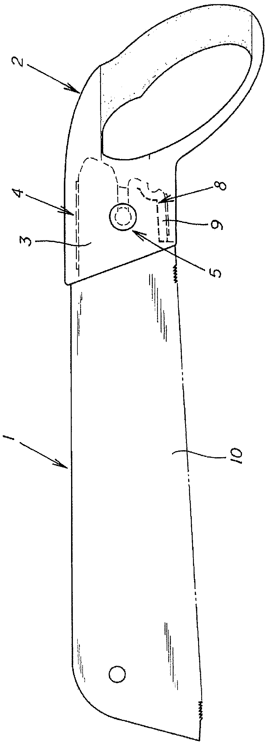
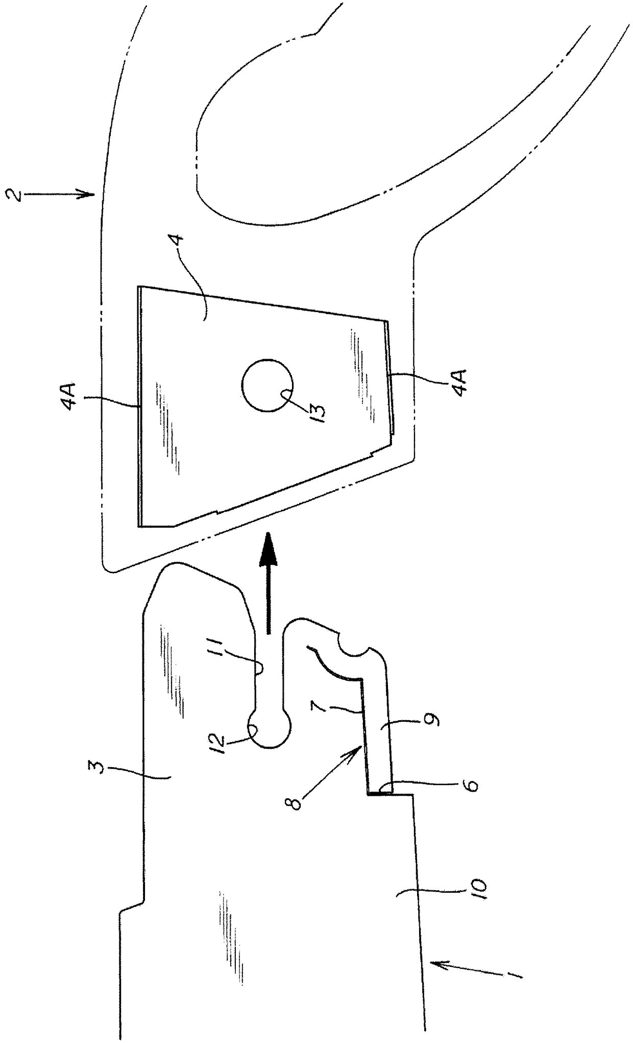
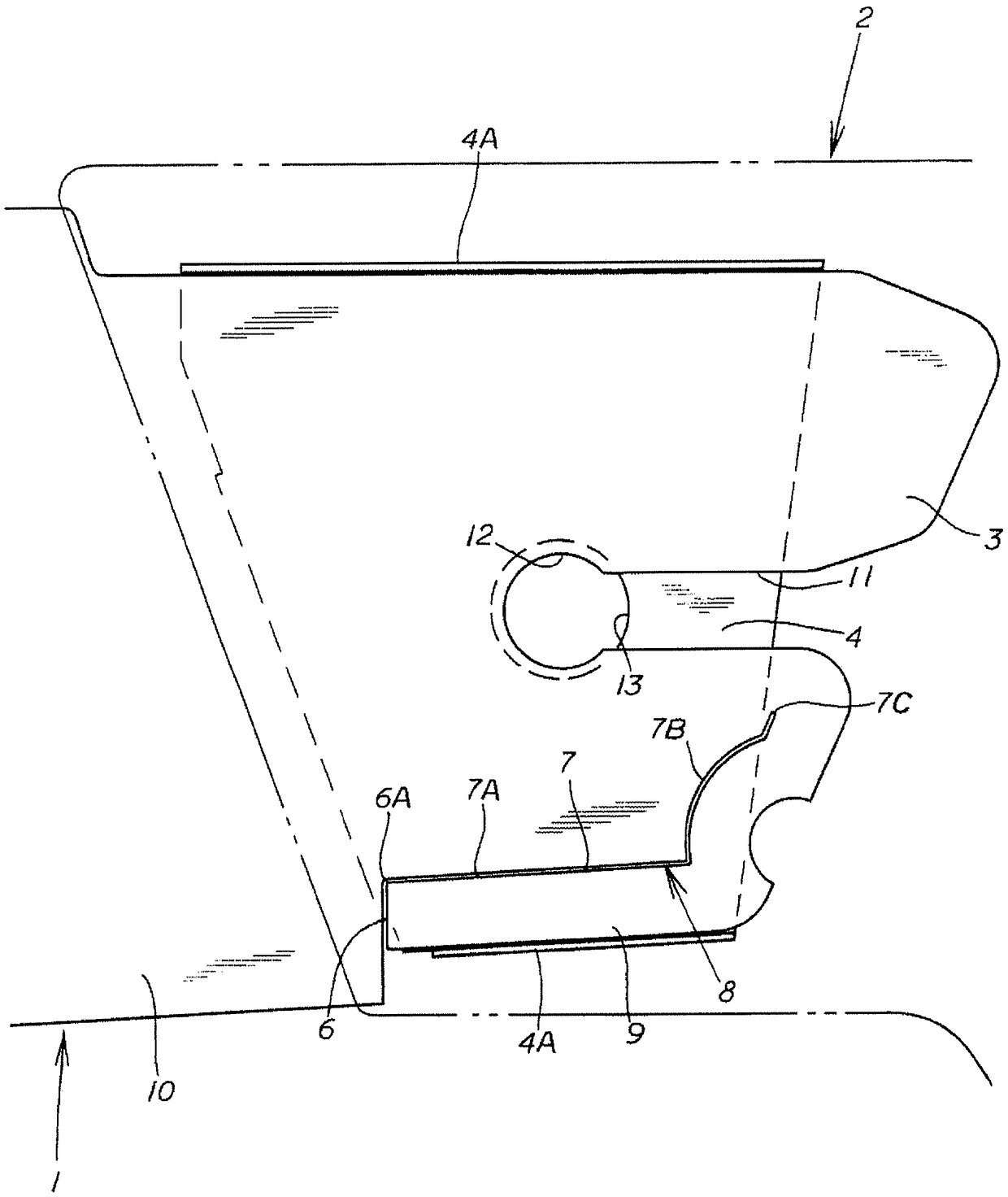
[0040] This embodiment is a blade-replacing saw composed of a saw blade 1 and a handle 2. When the upper handle insertion part 3 is inserted into the handle 2, the handle insertion part 3 is inserted into the guide member 4 built in the handle 2 to be guided, positioned and engaged with the guide member 4, so that the saw blade 1 becomes a predetermined insertion posture, and use the anti-off mechanism 5 provided on the handle 2 to suppress the pull-out of the handle insertion part 3 relative to the guide part 4, so that the handle insertion part 3 becomes a state locked with the guide part 4, and the saw blade 1 is installed as It cannot be pulled out from the handle 2 (cannot be disengaged). By releasing the anti-loosening mechanism 5, the locked state of the handle insertion part 3 on the guide member 4 is released, and the saw blade 1 is detached from the handle 2 so th...


PUM


Abstract

The purpose of the present invention is to provide a blade-replaceable saw in which, even when the width dimension of a handle insertion part is greater than the width dimension of a guide member, thehandle insertion part can be inserted into and engaged with the guide member. The blade-replaceable saw is configured such that: a slit part (8) is provided in the handle insertion part (3) of a sawblade (1), the slit part (8) being configured from a first slit section (6) that is formed inward from a side edge section of the handle insertion part (3), and a second slit section (7) that is formed continuous to the first slit section (6) and formed from a deep end portion (6A) of the first slit section (6) toward a tip side of the handle insertion part (3); and when a slit outer section (9) located outside the slit part (8) of the handle insertion part (3) receives an external force applied inward from the side edge section side, the slit outer section (9) is elastically moved or elastically deformed toward the inside by the slit part (8).

Description

technical field [0001] The invention relates to a blade-replacing saw which is formed by disposing a saw blade on a handle in a detachable and replaceable manner. Background technique [0002] The replacement blade saw is formed by installing the saw blade on the handle in a detachable and replaceable manner. The replacement blade saw is configured so that when the handle insertion part at the root of the saw blade is inserted into the handle, the inserted handle is inserted into the handle. The part is inserted into the guide member built in the handle and engaged to perform positioning. In the state of being positioned relative to the guide member, the detachment prevention mechanism provided on the handle is used to prevent the detachment. By The handle insert is positioned and secured on the guide member so that the saw blade is mounted and secured to the handle. [0003] In this replacement blade saw, in order to attach the saw blade to the handle without loosening, it...

Claims


Application Information

Patent Timeline
Patent Type & Authority Applications(China)
IPC IPC(8): B23D51/10B25G3/12B27B21/04B23D49/10B27B33/10
CPCB23D51/10B23D61/123B23D51/01
Inventor 石田雅史横田幸明
Owner TAKAGI CO LTD
Why Eureka
Try Eureka