Positioning device in portal design

A technology of positioning device and frame structure, applied in the direction of measuring device, mechanical measuring device, using mechanical device, etc., can solve the problem of not being monitored and so on

Active Publication Date: 2019-03-05
ETEL SA
View PDF9 Cites 0 Cited by
  • Summary
  • Abstract
  • Description
  • Claims
  • Application Information

AI Technical Summary

Problems solved by technology

[0007] In this positioning device, however, the positioning of the functional element perpendicular to

Method used


Image

  • Positioning device in portal design
  • Positioning device in portal design
  • Positioning device in portal design

Examples


Example Embodiment

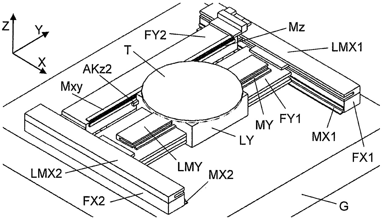
[0019] figure 1 A positioning device in a frame structure known in the prior art is shown. Two parallel linear guides FX1, FX2 are arranged on a base G, for example embodied as a granite block, and these linear guides hold the cross beam FY1 in a translational manner in the X direction. To move the crossbeam FY1, two linear motors LMX1, LMX2 are used, which are arranged parallel to the linear guides FX1, FX2 or integrated into the linear guides. At the cross beam FY1, the Y running vehicle LY is guided in a translational manner in the Y direction by means of another linear motor LMY.

[0020] The Y-car LY, as an example for functional elements, carries a worktable T on which wafers can be placed, and the wafers can then be processed or inspected by a tool fixedly arranged above the positioning device.

[0021] The positioning of the linear axis in the X and Y directions is achieved by measuring rods MX1, MX2, MY along the respective guides FX1, FX2, FY1. These measuring rods are s...


PUM


Abstract

The present invention provides a positioning device in a portal design. Two linear guides (FX1,FX2) are disposed parallel to each other on a base (G) and support the first and second cross members such that a first cross member (FX1) and a second cross member (FX2) are movable in a first direction. A Y-carriage (LY) has a functional element (T) and is supported on the first cross member (FY1) suchthat the Y-carriage (LY) and the functional element (T) are movable in a second direction (Y). A position-measuring device (Mxy,Mz,AKz2,Mxy1,AKxy1) is disposed on the second cross member (FY2) and the Y-carriage (LY) such that a position of the Y-carriage (LY) relative to the second cross member (FY2) is detectable by the position-measuring device. A Z-carriage (LZ) supports the functional element (T) such that the functional element (T) is movable relative to the Y-carriage (LY) in a third direction (Z). A further position-measuring device (AKxy2,AKxy2',Mxy2,Mxy2') is disposed on the Y-carriage (LY) and the functional element (T) such that a position of the functional element (T) relative to the Y-carriage (LY) is detectable by the further position-measuring device.

Description

Technical field [0001] The present invention relates to a positioning device in a frame structure, which has two driven linear axes extending in parallel for a first direction, and a beam that can translate along these linear axes, and the beam is in a second direction The functional element can be held in translation so that the functional element can be positioned in a plane between two parallel linear axes or parallel to the plane. The positioning device also includes another driven linear axis, with which the position of the functional element can be adjusted perpendicular to the plane, for example to assemble components or wiring to the circuit board. [0002] This positioning device is also called a platform drive or XY gantry, and is used in many technical fields. The processing of flat bases, such as wafers or circuit boards, is a typical application of this platform driver. Due to the continuous development of miniaturization, there is also a need for better and better ...

Claims


Application Information

Patent Timeline
IPC IPC(8): B25B11/02H05K3/30
CPCB25B11/02H05K3/30G05B19/402H05K3/0008G05B2219/37193G05B2219/40293H05K13/0015H05K13/0404G05B2219/37306G05B19/27H01L21/68G01D5/34G01B5/00F16M11/2085H01L21/681F16M11/2092F16M11/046
Inventor 戴维·英格拉姆劳伦特·海尼格
Owner ETEL SA
Why Eureka
Try Eureka