Electric machine

a technology of electric machines and sensors, applied in the direction of dynamo-electric machines, electrical apparatus, magnetic circuit rotating parts, etc., can solve the problems of significant tolerability of the position of the sensor, reduce the likelihood of any relative movement, reduce the impact of the position sensor holder on the available space within the motor, and reduce the likelihood of any damage

Active Publication Date: 2019-04-18
DYSON TECH LTD
View PDF0 Cites 1 Cited by
  • Summary
  • Abstract
  • Description
  • Claims
  • Application Information

AI Technical Summary

Benefits of technology

[0006]As a result, the magnet is protected by the bearing seat. Furthermore, because the bearing seat provides a mounting point for the rotor assembly as well as a mounting point for the position sensor assembly, tight control over the relative positioning can more easily be achieved. This in turn, provides a more accurate position measurement to the control system of the electric machine which can improve the machine's performance.
[0019]The sensor magnet and the second magnet may be fixed to the shaft on either side of the bearing. As a result, a better balancing of the components on the shaft can be achieved, and the life of the bearing can be improved.

Problems solved by technology

However, for electric machines that are relatively small and / or where relatively high efficiency is required, tolerances in the position of the sensor present a significant problem.

Method used


Image

  • Electric machine
  • Electric machine
  • Electric machine

Examples


Embodiment Construction

[0025]The term “axially” is used herein to describe a direction parallel to the rotational axis of the shaft of the electric machine, and could alternatively be referred to as “longitudinally”.

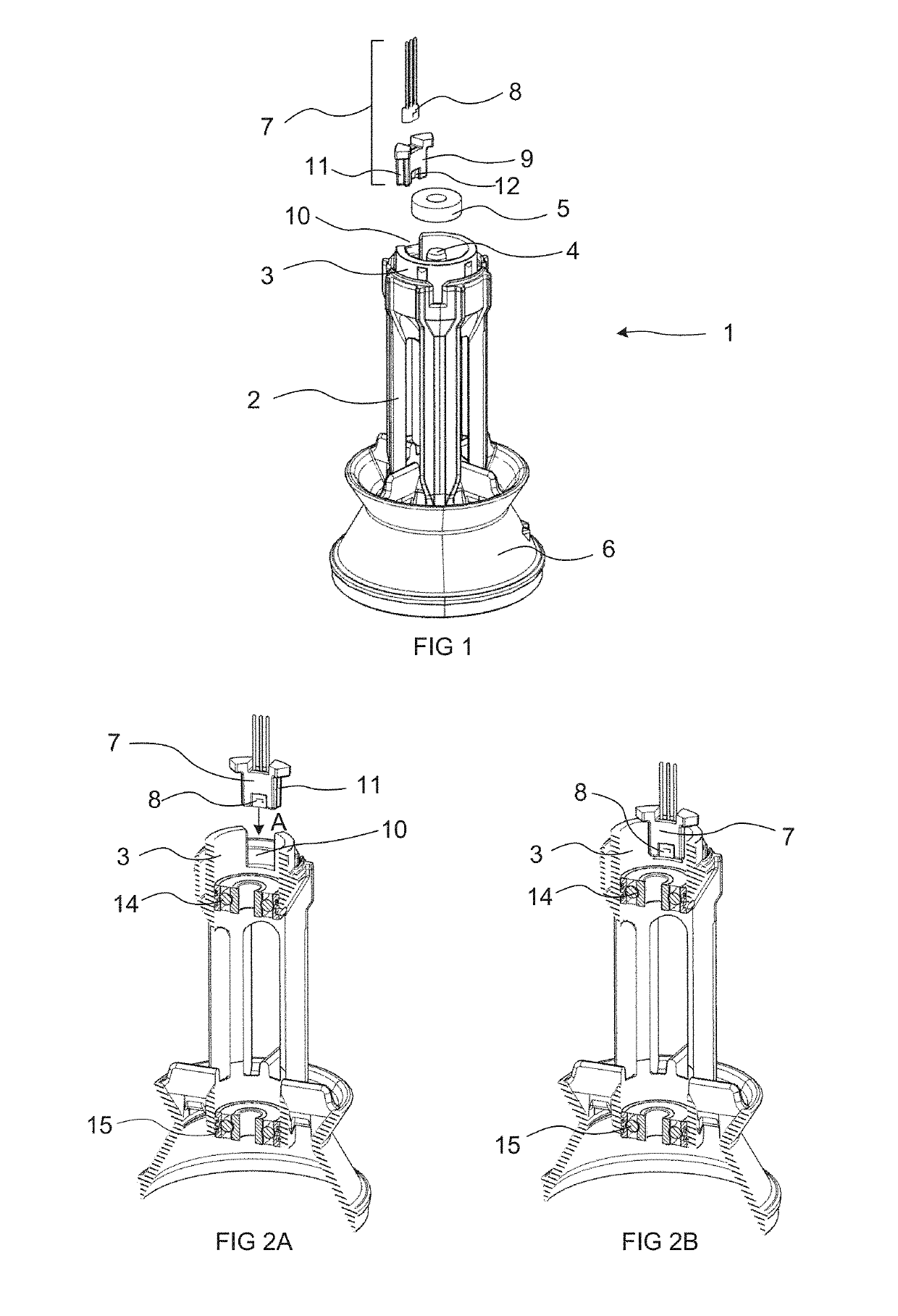
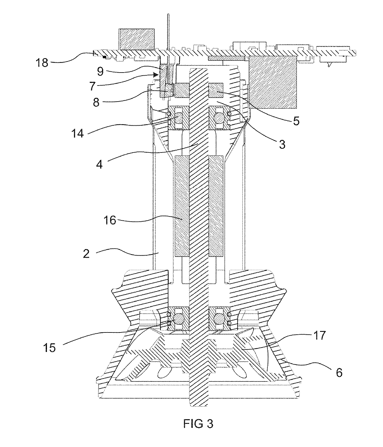
[0026]FIG. 1 shows a partly exploded perspective view of part of an electric machine in the form of a compressor 1. Certain components, such as control electronics and a stator assembly, are not shown for clarity. The compressor 1 comprises a frame 2, to which the stator assembly and rotor assembly of the motor can be mounted. Other components, not shown, can also be mounted to the frame, for example an outer casing, or a diffuser.

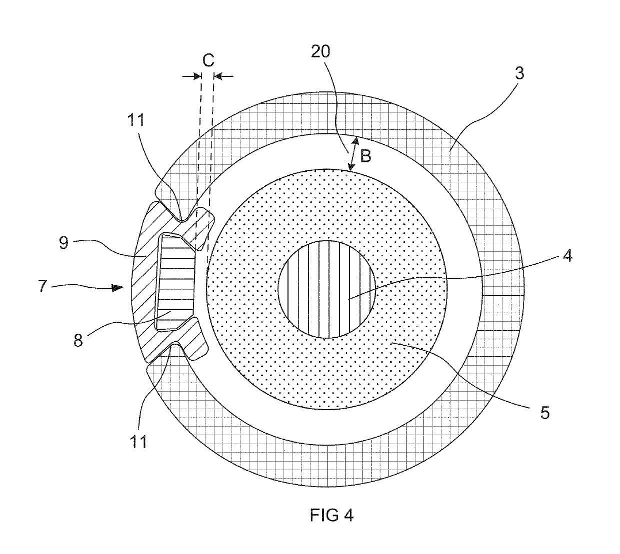
[0027]Part of a rotor assembly can be seen in FIG. 1. The rotor assembly comprises a shaft 4 on which, when assembled, is mounted a magnet 5. The magnet 5 in the embodiment of FIG. 1 is a sensor magnet. The rotor assembly comprises other components not visible in FIG. 1, including a rotor core permanent magnet, first and second balancing rings, and first and second b...


PUM


Abstract

An electric machine comprising: a frame; and a rotor assembly comprising a shaft to which is mounted at least one bearing and at least one magnet; the frame comprising a bearing seat to which the bearing of the rotor assembly is mounted, and wherein the bearing seat extends axially beyond the bearing to surround the magnet, and the bearing seat comprises locating features for holding a position sensor assembly relative to the magnet.

Description

REFERENCE TO RELATED APPLICATIONS[0001]This application claims the priority of United Kingdom Application No. 1716693.5, filed Oct. 12, 2017, the entire contents of which are incorporated herein by reference.FIELD OF THE INVENTION[0002]The present invention relates to an electric machine.BACKGROUND OF THE INVENTION[0003]The output power of an electric machine is critically dependant on accurate synchronisation of phase energisation and rotor position. Accordingly, in electric machines such as high speed motors, it is important to have an accurate measurement of the angular position of the motor.[0004]For many motors, the tolerance in the position of the sensor is not a problem. This may be because the size of the electric machine is relatively large and thus the tolerance in the position of the sensor is small in comparison to the circumference of the rotor. Consequently, any positional tolerance in the sensor results in a negligible offset in the electrical angle of the zero-crossi...

Claims


Application Information

Patent Timeline
Patent Type & Authority Applications(United States)
IPC IPC(8): H02K11/215H02K7/00H02K5/16H02K1/27
CPCH02K11/215H02K7/003H02K5/161H02K1/27H02K5/1732H02K2211/03H02K2213/03H02K11/21H02K5/16H02K29/06H02K29/08H02K29/14
Inventor WELLS, ALEXANDER THOMAS
Owner DYSON TECH LTD
Why Eureka
Try Eureka