Positioning device in frame construction

A positioning device and frame structure technology, applied in the direction of measuring devices, mechanical measuring devices, mechanical devices, etc., can solve the problems of not being monitored, and achieve the effect of accurate position measurement and simplified structure

Active Publication Date: 2022-04-15
ETEL SA
View PDF9 Cites 0 Cited by
  • Summary
  • Abstract
  • Description
  • Claims
  • Application Information

AI Technical Summary

Problems solved by technology

[0007] In this positioning device, however, the positioning of the functional element perpendicular to the base is not monitored, which positioning is achieved by means of additional actuated linear guides

Method used


Image

  • Positioning device in frame construction
  • Positioning device in frame construction
  • Positioning device in frame construction

Examples


Embodiment Construction

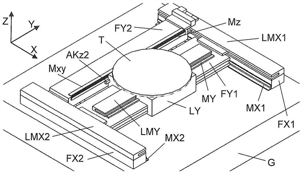
[0030] figure 1 A positioning device in a frame structure known from the prior art is shown. Two parallel linear guides FX1 , FX2 are arranged on a base G, for example in the form of a granite block, which hold the transverse beam FY1 translatably in the X direction. Two linear motors LMX1 , LMX2 are used for moving the transverse beam FY1 , which are arranged parallel to the linear guides FX1 , FX2 or are integrated into the linear guides. On the transverse beam FY1, the Y-travel carriage LY is guided in translation in the Y-direction by means of a further linear motor LMY.

[0031] The Y carriage LY carries, as an example for a functional element, a table T on which wafers can be placed, which can then be processed or inspected by tools arranged in a fixed position above the positioning device.

[0032] The positioning of the linear axes in the X and Y directions is carried out along the respective guides FX1, FX2, FY1 by means of measuring rods MX1, MX2, MY which are scan...


PUM


Abstract

The invention relates to a positioning device in a frame structure with two linear guides (FX1, FX2) arranged parallel to each other on a base (G), which make a first beam (FY1) and a second beam (FY2) Movably held in the first direction, the Y trolley (LY) is held movably in the second direction (Y) by means of a functional element (T) at the first beam (FY1) and at the second beam (FY2 ) and the Y running car (LY) are arranged to detect the position measuring device (Mxy, Mz, AKz2, Mxy1, AKxy1) for detecting the position of the Y running car (LY) relative to the second beam (FY2). The functional element (T) is held movably in a third direction (Z) by means of the Z carriage (LZ) relative to the Y carriage (LY), and the Y carriage (LY) and the functional element (T) are arranged for Further position measuring devices (AKxy2, AKxy2', Mxy2, Mxy2') for detecting the position of the functional element (T) relative to the Y carriage (LY).

Description

technical field [0001] The invention relates to a positioning device in a frame structure having two parallel-extending actuated linear axes for a first direction and a beam translatable along these linear axes, the beam being in a second direction The functional element is held in translation such that it can be positioned in a plane between two parallel linear axes or parallel to this plane. The positioning device also includes a further driven linear axis, by means of which the position of the functional element can be adjusted perpendicular to the plane, for example for mounting components or wiring a circuit board. [0002] Such positioning devices are also known as platform drives or XY gantry and are used in many technical fields. Processing of flat substrates such as wafers or circuit boards is a typical application for this type of platform drive. Due to the ever-growing miniaturization, better and better positioning accuracy is also required here. Background tech...

Claims


Application Information

Patent Timeline
Patent Type & Authority Patents(China)
IPC IPC(8): B25B11/02H05K3/30
CPCB25B11/02H05K3/30G05B19/402H05K3/0008G05B2219/37193G05B2219/40293H05K13/0015H05K13/0404G05B2219/37306G05B19/27H01L21/68G01D5/34G01B5/00F16M11/2085H01L21/681F16M11/2092F16M11/046
Inventor 戴维·英格拉姆劳伦特·海尼格
Owner ETEL SA
Why Eureka
Try Eureka