
Double-roller electric-pole centrifuge with high-temperature curing function

A technology of high-temperature maintenance and centrifuge, applied in the direction of manufacturing tools, ceramic molding machines, etc., can solve the problems of inability to meet the production needs of large quantities, affect the demoulding quality and demoulding efficiency, and low work efficiency, so as to shorten the demoulding The effect of saving time, simplifying equipment and improving production efficiency

Inactive Publication Date: 2019-03-05
湖北红业建材科技开发有限公司
View PDF1 Cites 1 Cited by
  • Summary
  • Abstract
  • Description
  • Claims
  • Application Information

AI Technical Summary

Problems solved by technology

[0002] The equipment usually used in the production of electric poles is a centrifuge, and the centrifuges commonly used at present are single-roller centrifuges. Using the above-mentioned equipment for electric pole production can only produce one electric pole at a time, and the work efficiency is low. For example, it is disclosed in CN 205630967 U A kind of centrifuge for making electric poles uses a single roller, which cannot meet the production needs of large quantities;
[0003] In addition, after the production of traditional electric poles is completed, natural curing is adopted, and after the curing is completed, it is demoulded. The above-mentioned process is time-consuming, which seriously affects the demoulding quality and demoulding efficiency. It is necessary to design a cooperating The high temperature device used in the centrifuge assists the demoulding process of the pole

Method used


Image

  • Double-roller electric-pole centrifuge with high-temperature curing function
  • Double-roller electric-pole centrifuge with high-temperature curing function
  • Double-roller electric-pole centrifuge with high-temperature curing function

Examples


Embodiment Construction

[0022] Embodiments of the present invention will be further described below in conjunction with the accompanying drawings.

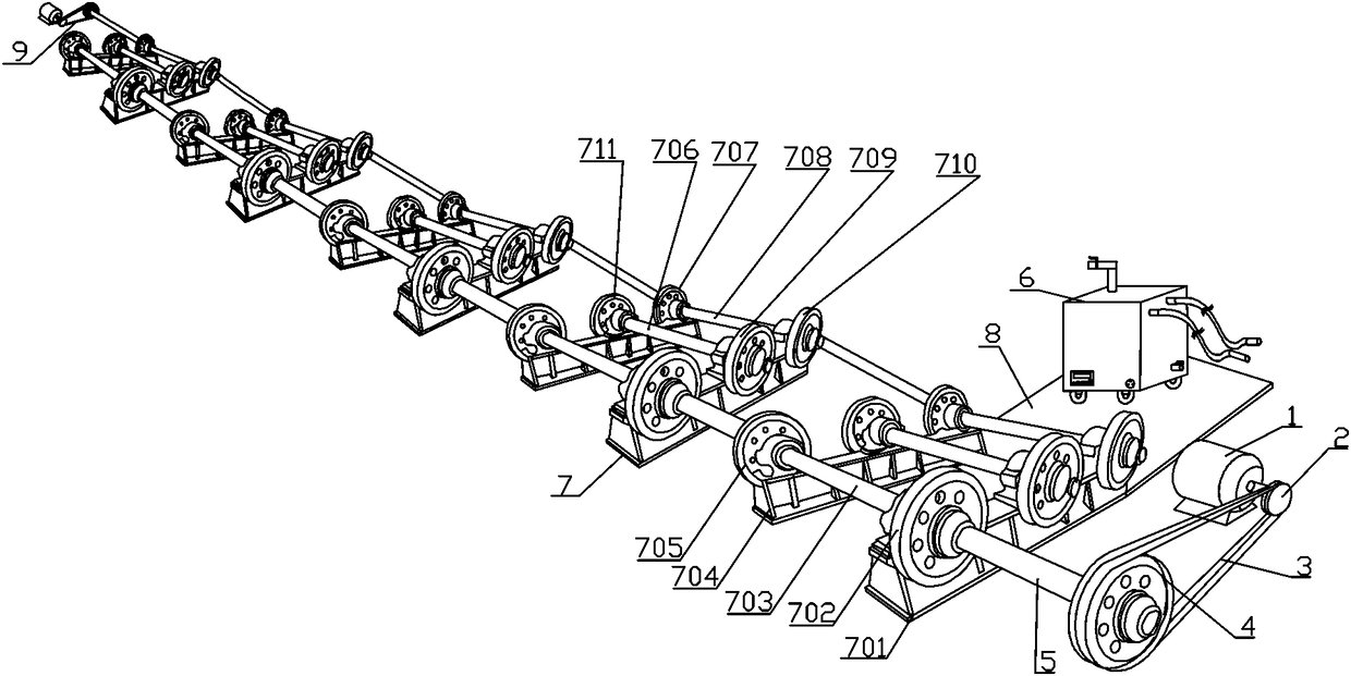
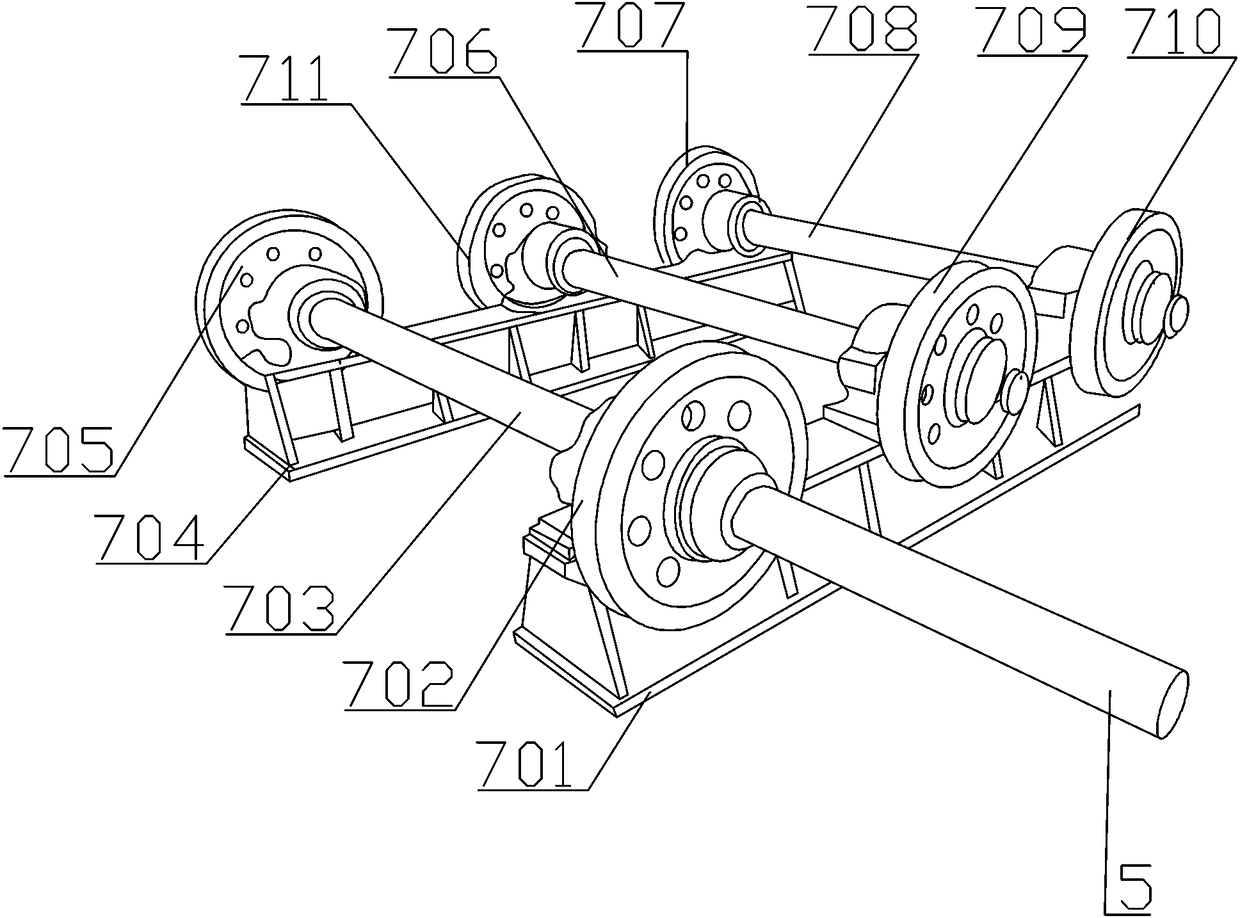
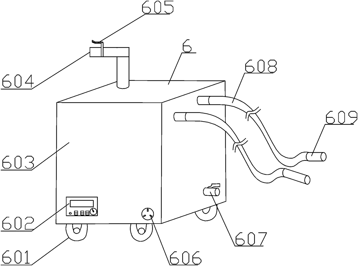
[0023] see Figure 1-3 , a double-roller electric pole centrifuge with high-temperature maintenance function, which includes multiple sets of centrifugal assemblies 7 connected in series; the head centrifugal assembly and tail centrifugal assembly are respectively connected with two sets of driving mechanisms 9, and drive the centrifugal assembly 7 to drive the mold Rotate; a high-temperature maintenance device 6 is provided on the side bottom plate 8 of the head centrifugal assembly;

[0024] Further, each set of centrifugal assemblies 7 includes a first base 701 and a second base 704; between the first base 701 and the second base 704, a first driving idler assembly, a central idler assembly and a second base are installed side by side. Two driving roller assemblies; the first driving roller assembly includes a first driving shaft 703, and the two end...


PUM


Abstract

The invention provides a double-roller electric-pole centrifuge with a high-temperature curing function. The double-roller electric-pole centrifuge comprises a plurality of groups of centrifugal components which are connected in series with one another, wherein a head centrifugal component and a tail centrifugal component are correspondingly connected with two groups of driving mechanisms, and thecentrifugal components are driven to bring two molds to rotate; a high-temperature curing device is arranged on a side bottom plate of the heat centrifugal component; and each group of centrifugal components comprises a first base and a second base, and a first active supporting roller component, a central supporting roller component and a second active supporting roller component are parallellymounted between the first base and a second base. By the adoption of the double-roller electric-pole centrifuge, the two molds can be driven at the same time; accordingly, the centrifugal production of two electric poles at a time can be achieved, the production efficiency can be improved, and the equipment cost can be reduced; and furthermore, the demolding process can be accelerated by adoptingthe high-temperature curing process, the production time can be shortened, and the working efficiency can be improved.

Description

technical field [0001] The invention relates to the field of pole processing and production equipment, in particular to a double-roller pole centrifuge with a high-temperature maintenance function. Background technique [0002] The equipment usually used in the production of electric poles is a centrifuge, and the centrifuges commonly used at present are single-roller centrifuges. Using the above-mentioned equipment for electric pole production can only produce one electric pole at a time, and the work efficiency is low. For example, it is disclosed in CN 205630967 U A kind of centrifuge for making electric poles uses a single roller, which cannot meet the production needs of large quantities; [0003] In addition, after the production of traditional electric poles is completed, natural curing is adopted, and after the curing is completed, it is demoulded. The above-mentioned process is time-consuming, which seriously affects the demoulding quality and demoulding efficiency....

Claims


Application Information

Patent Timeline
IPC IPC(8): B28B21/30B28B11/24
CPCB28B21/30B28B11/24
Inventor 陈良洪
Owner 湖北红业建材科技开发有限公司
Learn More