

Cooling structure suitable for high-pressure turbine of gas turbine
A cooling structure, high-pressure turbine technology, applied in mechanical equipment, engine components, machines/engines, etc., can solve problems such as difficulty in outflow from the pressure surface of the channel, uneven pressure distribution at the outlet of the slot, and cooling of the pressure surface of the leakage channel.
- Summary
- Abstract
- Description
- Claims
- Application Information
AI Technical Summary
Problems solved by technology
Method used
Image

Examples
Embodiment Construction
[0026] The present invention will be further described below in conjunction with specific embodiment and accompanying drawing, set forth more details in the following description so as to fully understand the present invention, but the present invention can obviously be implemented in many other ways different from this description, Those skilled in the art can make similar promotions and deductions based on actual application situations without violating the connotation of the present invention, so the content of this specific embodiment should not limit the protection scope of the present invention.
[0027] It should be noted that these and other subsequent drawings are only examples, which are not drawn according to the same scale, and should not be taken as limitations on the protection scope of the actual claims of the present invention.
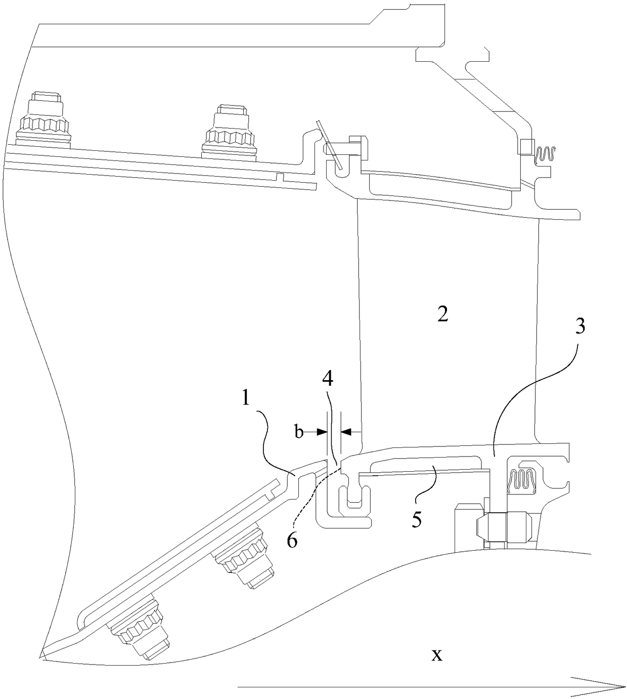
[0028] Such as figure 1 As shown, the gap between the ring load-bearing wall 1 in the combustion chamber and the end surface of the b...
PUM
| Property | Measurement | Unit |
|---|---|---|
| Aperture | aaaaa | aaaaa |
Abstract
Description
Claims
Application Information