
Sealing assembly and sealing ring therein

A technology of sealing components and sealing rings, which is applied in the direction of engine sealing, machine sealing ring testing, engine components, etc., can solve the problems that the sealing ring can no longer be used, cannot detect the gradual change of the sealing ring condition, etc., and achieves less danger of assembly errors. The effect of simplification and simple manufacturing

Active Publication Date: 2020-06-09
CARL FREUDENBERG KG
View PDF8 Cites 0 Cited by
  • Summary
  • Abstract
  • Description
  • Claims
  • Application Information

AI Technical Summary

Problems solved by technology

[0010] Care must be taken in this constructional design of the seal assembly: Gradual changes in the condition of the seal cannot be detected
Closing through the circuit only means: the seal is no longer usable and must be replaced immediately

Method used


Image

  • Sealing assembly and sealing ring therein
  • Sealing assembly and sealing ring therein

Examples


Embodiment Construction

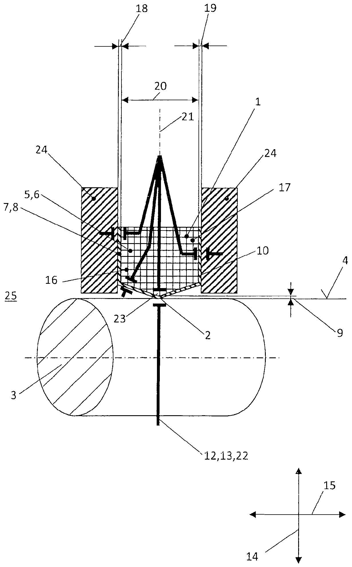
[0041] exist figure 1 An embodiment is shown in , as already disclosed in the earlier application mentioned above.

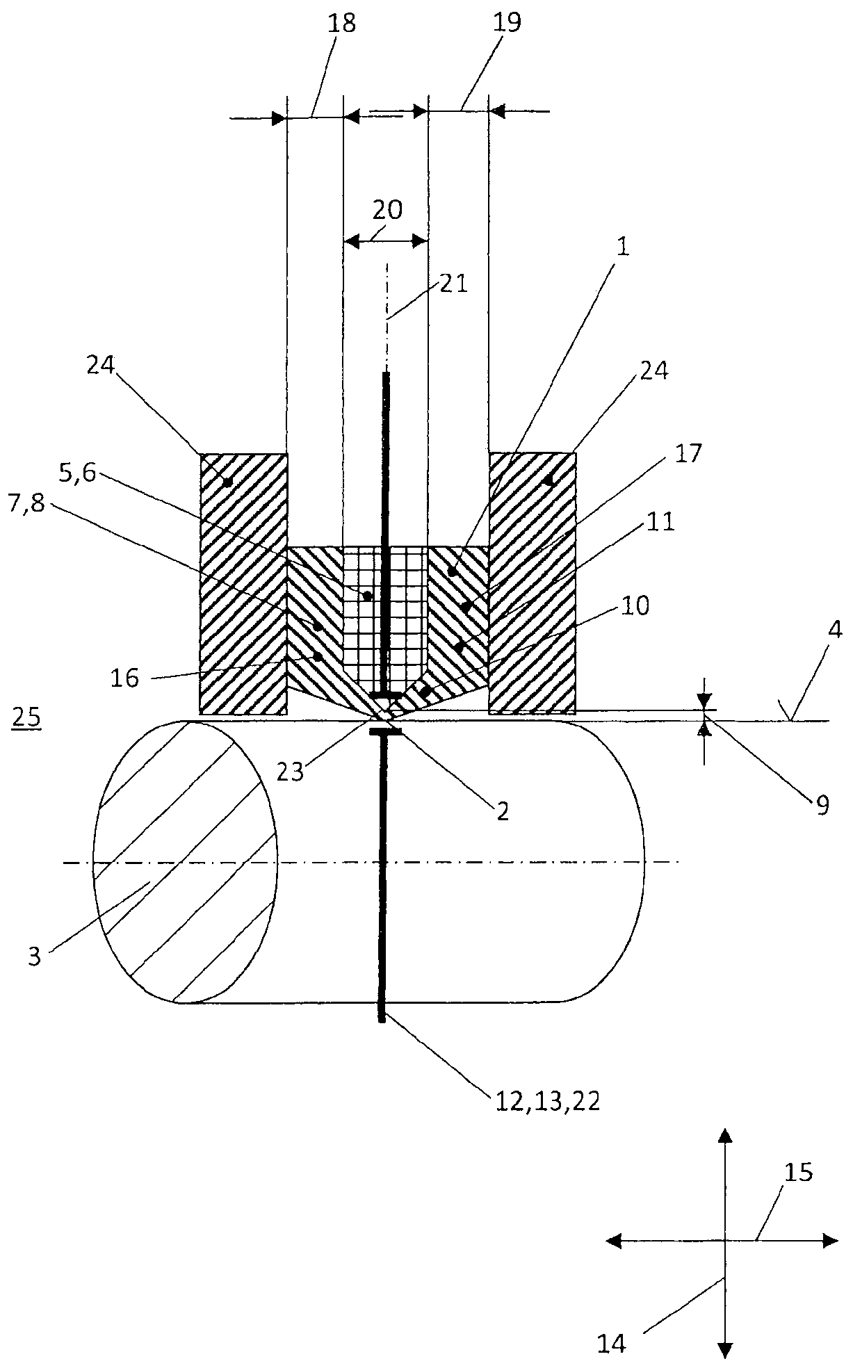
[0042] The sealing arrangement comprises a sealing ring 1 with a dynamically loaded sealing lip 2 which, with radial prestressing, tightly surrounds a surface 4 to be sealed of a mechanical part 3 to be sealed.

[0043] The surface 4 to be sealed is electrically conductive.

[0044] The sealing ring 1 comprises a core 5 which is surrounded by a cladding 7 in the region of its end faces 16 , 17 and on the side facing the surface 4 to be sealed.

[0045] The core 5 consists of an electrically conductive material 6 , while the cladding 7 consists of an electrically insulating material 8 .

[0046] A wear sensor 12 is shown schematically, which includes an electrical measuring device 13 for detecting the wear state of the sealing ring 1 .

[0047] Seen in the sectional illustration shown here, the cladding 7 has overall a constant material thickness 9 , 10 , 11 ....


PUM


Abstract

The invention relates to a sealing assembly comprising: a sealing ring (1) with at least one sealing lip (2) subjected to dynamic loads; a mechanical part (3) to be sealed with a surface (4) to be sealed, said The sealing surface is electrically conductive and is tightly surrounded by the sealing lip (2) with radial pretension, wherein the sealing ring (1) has a core (5) of electrically conductive material (6) and an electrical a cladding (7) of insulating material (8) having a material thickness (9, 10, 11), at least partially surrounding the core (5) and including said sealing lip; and a wear detector ( 12) The wear detector comprises an electrical measuring device (13) for detecting the wear condition of the sealing ring, wherein, viewed in section, the material thickness (9) of the sealing lip along the radial direction (14) is smaller than that of the packing The material thickness of the rest of the layer (10, 11). The invention also relates to a sealing ring.

Description

technical field [0001] The invention relates to a sealing assembly comprising: a sealing ring with at least one dynamically loaded sealing lip; a mechanical part to be sealed with a surface to be sealed, which is electrically conductive and Sealed with radial pretension by a sealing lip, wherein the sealing ring has a core of an electrically conductive material and a cladding of an electrically insulating material with a material thickness that encloses the core at least partially ground surrounding and including said sealing lip; and a wear detector including an electrical measurement device for detecting a wear condition of the seal ring. [0002] In addition, the present invention also relates to a sealing ring in the sealing assembly, as mentioned above. Background technique [0003] Such a sealing assembly and such a sealing ring are disclosed in the earlier application DE 10 2016 012 552.7. [0004] The electrically insulating cladding has a material thickness that i...

Claims


Application Information

Patent Timeline
Patent Type & Authority Patents(China)
IPC IPC(8): F16J15/3296
CPCF16J15/3296G01M13/005F16J15/34F16J15/3284
Inventor O·纳尔沃尔德S·辛德林格F·劳尔B·特拉伯J·门策尔T·克拉默
Owner CARL FREUDENBERG KG
Learn More