Aerial vehicle imaging and targeting system

An imaging and tracking system technology, applied in the field of virtual reality systems, can solve problems such as inapplicability

Active Publication Date: 2019-03-05
AURORA FLIGHT SCI CORP
View PDF6 Cites 20 Cited by
  • Summary
  • Abstract
  • Description
  • Claims
  • Application Information

AI Technical Summary

Problems solved by technology

while these air defense systems are suitable for target aircraft located at a distance, they are not suitable for nearside (ie, nearby) fast-moving objects / aircraft

Method used


Image

  • Aerial vehicle imaging and targeting system
  • Aerial vehicle imaging and targeting system
  • Aerial vehicle imaging and targeting system

Examples


Embodiment Construction

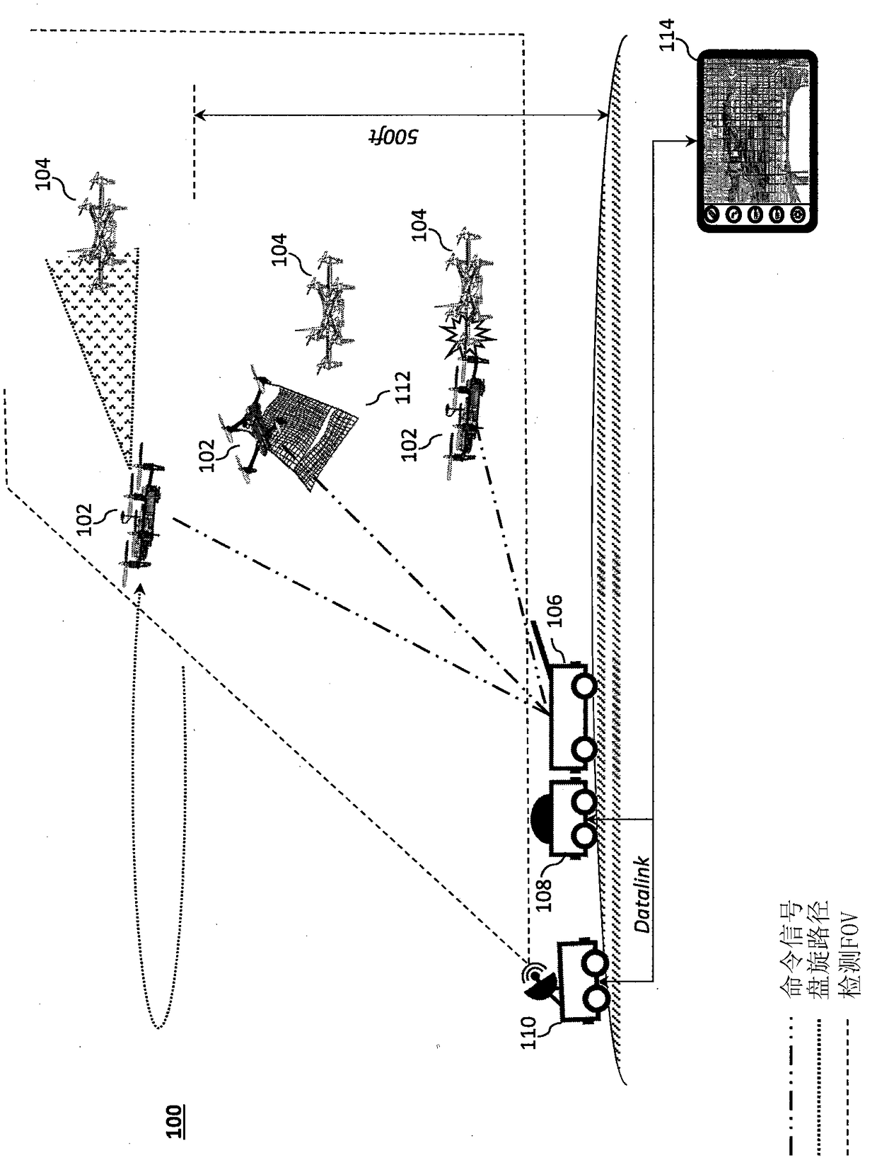
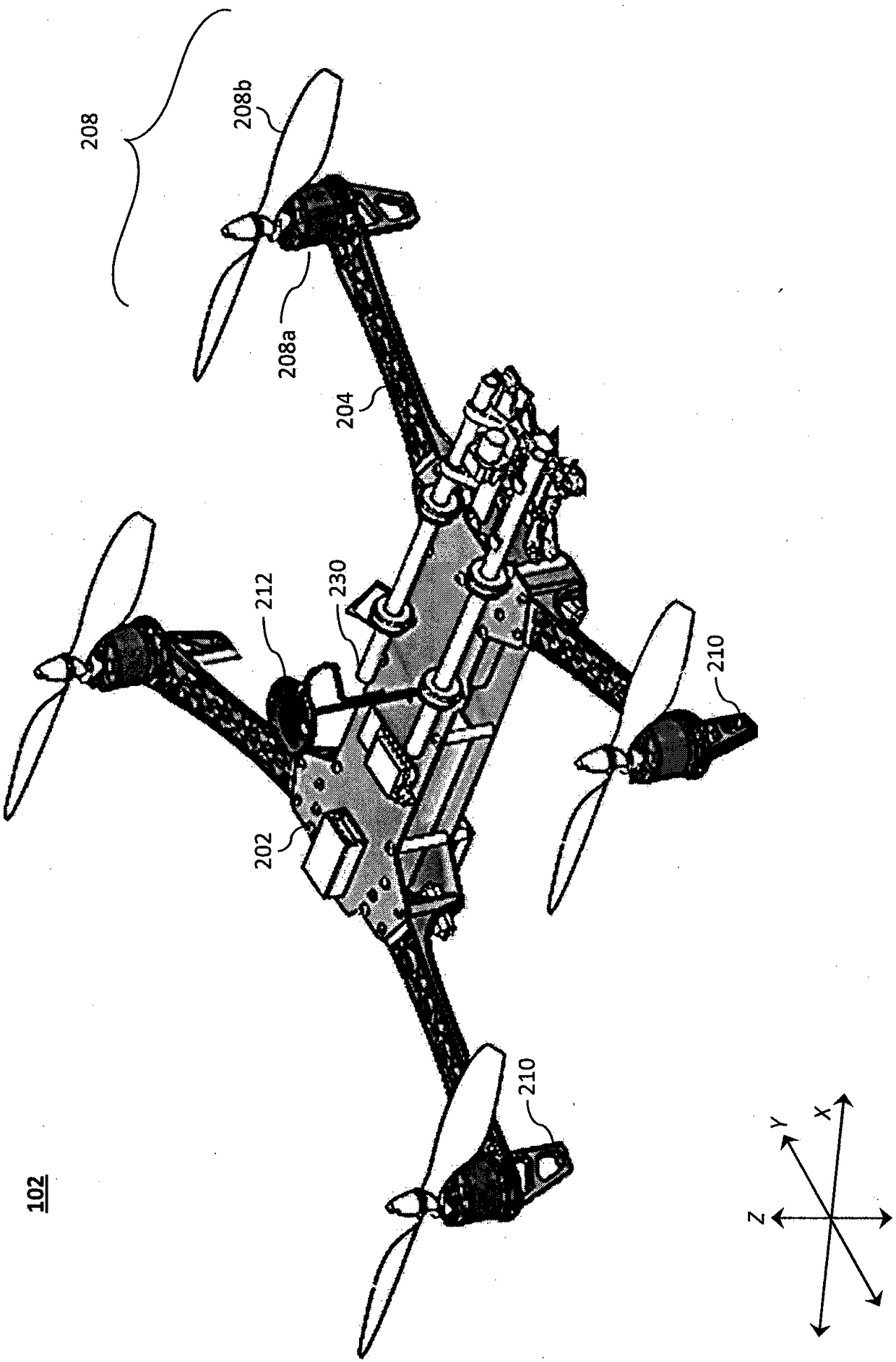
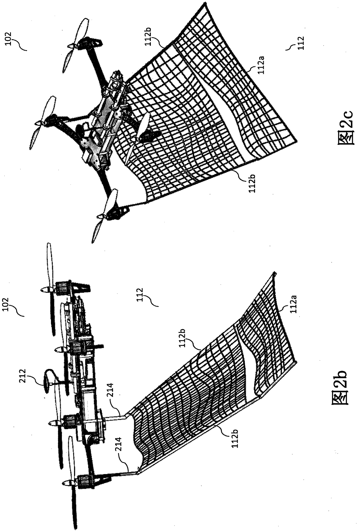
[0057] Preferred embodiments of the present invention will be described below with reference to the accompanying drawings. The components in the figures are not necessarily to scale, emphasis instead being placed upon clearly illustrating the principles of the present embodiments. For example, the dimensions of elements may be exaggerated for clarity and convenience of description. Furthermore, where possible, the same reference numbers are used throughout the drawings to refer to the same or like elements of the embodiments. In the following description, well-known functions or constructions are not described in detail since they would obscure the invention in unnecessary detail. No language in the specification should be construed as indicating any non-claimed element as essential to the practice of the embodiments.

[0058] Recitations of ranges of values ​​herein are not intended to be limiting, but instead refer individually to any and all values ​​falling within the ra...


PUM


Abstract

The subject disclosure relates to a tracking system to mount to an aircraft and to image and track a target aircraft. The tracking system may include a structured light source 304 operatively coupledto a processor, an inertial measurement unit (IMU) 224c operatively coupled with the processor, a mirror 306 to steer light from the light source toward the target aircraft, and a stereo-vision systemhaving a first camera and a second camera. The IMU may be configured to generate position data representing a position of the aircraft. The stereo-vision system may be operatively coupled to the processor and configured to determine a 3D position of the target aircraft as a function of the position data. The processor may be configured to adjust the mirror position as a function of a mirror position.

Description

[0001] cross application [0002] This application, filed August 25, 2017 under the requirements of 35 U.S.C. § 119(e) (35 U.S.C. § 119(e)) is entitled "Aerial Vehicle Imaging and Targeting System" US Provisional Patent Application Serial No. 62 / 550,331, the contents of which are incorporated herein by reference. technical field [0003] The present disclosure relates to aircraft, aerial systems, and virtual reality systems for use with aerial systems. Background technique [0004] Existing air defense systems are not suitable for defending against invasive low-cost unmanned aerial vehicles (UAVs), such as commercially available UAVs, which may be used to carry improvised weapons and / or surveillance systems. For example, traditional defense systems against rockets, artillery, and mortars often involve anti-aircraft missiles or guns (eg, Phalanx Close-In Weapon System, CWIS). However, such systems are often impractical and cost-prohibitive due to their relative cost compare...

Claims


Application Information

Patent Timeline
Patent Type & Authority Applications(China)
IPC IPC(8): F41H11/02
CPCF41H11/02G01S17/66G01S17/89G01B11/25G01B11/2545G05D1/0094F41H11/04F41H13/005G01S17/86H04N13/239G02B26/0833B64C39/024G03B15/006F41H13/00B64U10/10B64U2101/30H04N13/254B64D47/08G06V20/20
Inventor J-W·崔J·D·帕杜阿诺
Owner AURORA FLIGHT SCI CORP
Why Eureka
Try Eureka