Heat sink fixing structure

A technology for fixing structures and heat sinks, which is applied to electric solid-state devices, semiconductor/solid-state device components, semiconductor devices, etc., can solve the problems of inability to self-lock, short-circuit electronic products, and falling off of fixed structures, and achieve simple structure and self- The lock is stable and firm, and the installation is fast.

Active Publication Date: 2020-07-14
AMBIT MICROSYSTEMS (SHANGHAI) LTD
View PDF4 Cites 0 Cited by
  • Summary
  • Abstract
  • Description
  • Claims
  • Application Information

AI Technical Summary

Problems solved by technology

[0002] In existing electronic products, there is a central processing unit inside the main casing, which generates heat during operation, so the heat sink is fixed on the main board to dissipate heat from the central processing unit. The traditional fixed structure for fixing the heat sink includes The fixing column and the spring only hook the main board through the hook at the lower end of the fixing column, and cannot be self-locked. When the electronic product is working, the fixed structure may easily fall off due to vibration. In addition, the spring is made of metal. When the fixed structure falls off, the electronic product Prone to short circuit and easy to cause electromagnetic interference

Method used


Image

  • Heat sink fixing structure
  • Heat sink fixing structure
  • Heat sink fixing structure

Examples


Embodiment Construction

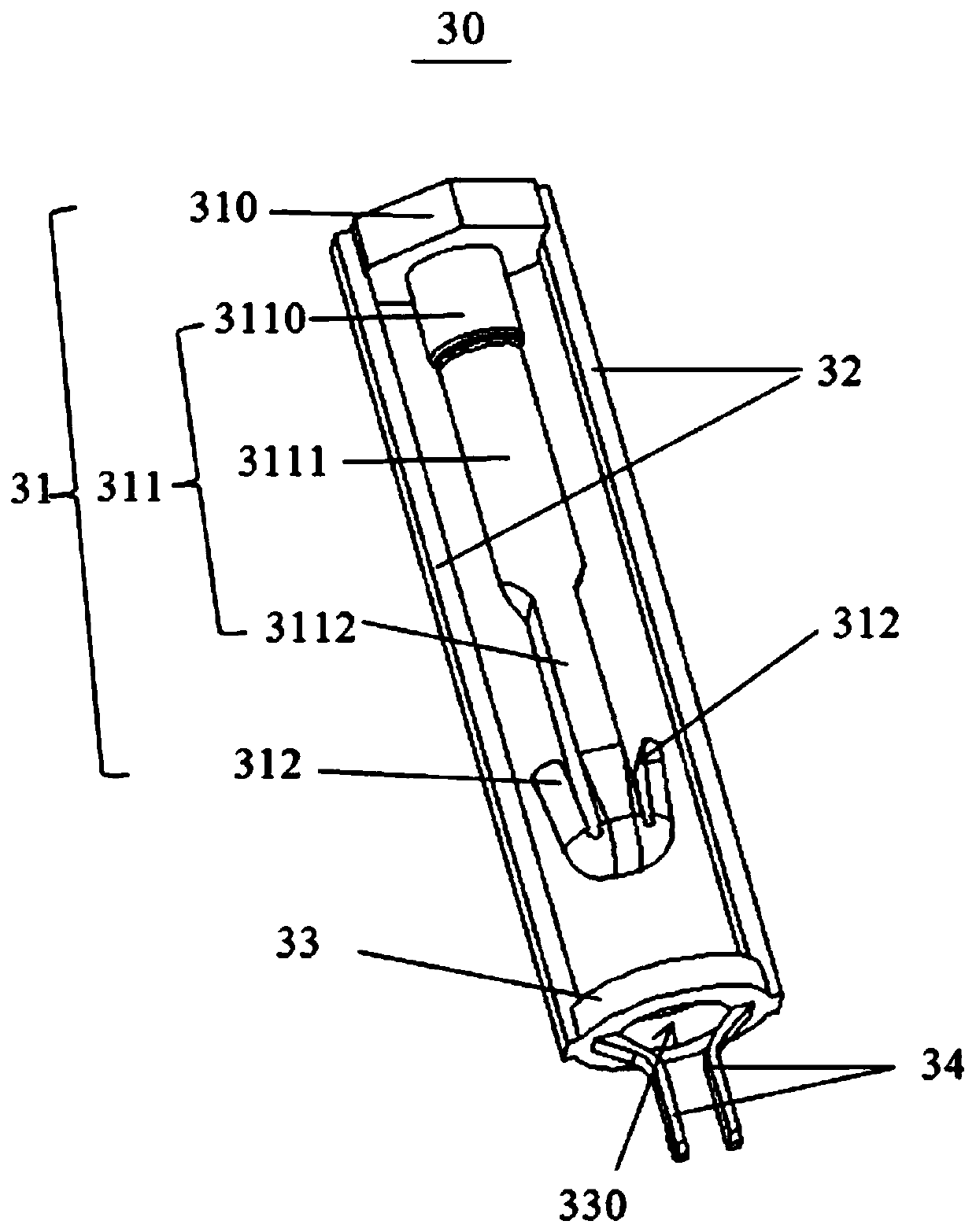
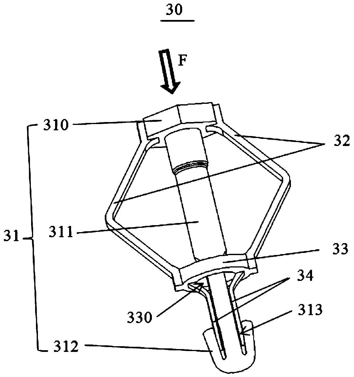
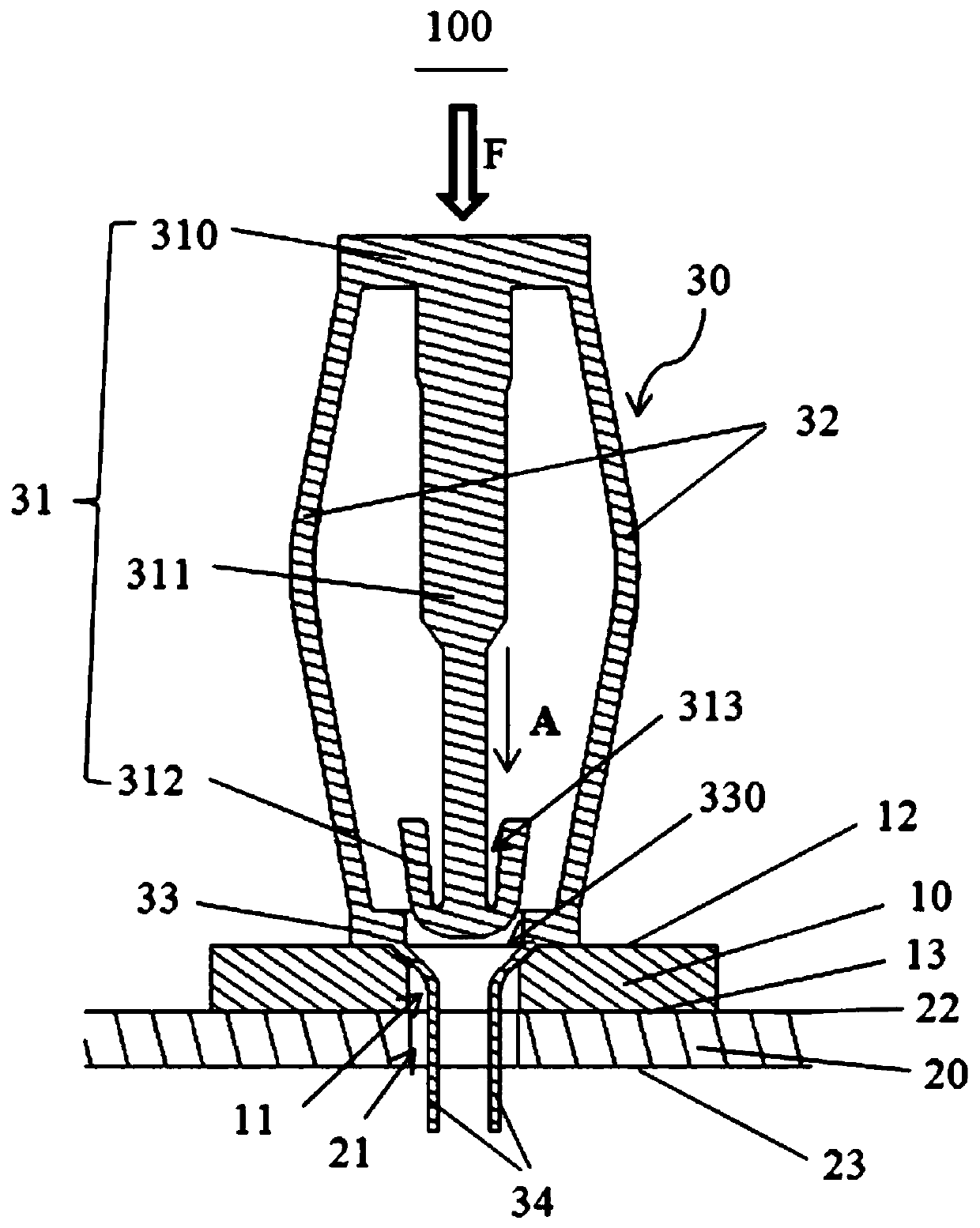
[0026] Such as figure 1 and figure 2 As shown, the locking member 30 includes a fixing column 31, an elastic arm 32, a washer 33 and a locking arm 34. The fixing column 31 includes a column head 310, a column body 311, a hook 312 and a receiving groove between the column body 311 and the hook 312. 313. The post 310 is a hexagon or other shapes, and the post 311 includes a first section 3110 connecting the post 310, a second section 3112 connecting the hook 312, and an intermediate section 3111 connecting the first section 3110 and the second section 3112, wherein The first section 3110 and the middle section 3111 are cylindrical, and the second section 3112 is inscribed from the end of the middle section 3111, that is, the second section 3112 is formed by two opposite planes and two opposite arc surfaces, and the hook 312 extends from the ends of the two planes It can be seen that the hook 312 expands outward when no force is applied, and the hook 312 is elastic, and the re...


PUM


Abstract

The invention provides a cooling fin fixing structure, which is suitable for accommodating of cables of electronic products. The fixing structure comprises a cooling fin with a first locking hole, a mainboard with a second locking hole, and a locking piece which comprises a fixed column, an elastic arm, a gasket and a locking arm; the fixed column comprises a column body and a clamping hook; a containing groove is formed between the column body and the clamping hook; the gasket is provided with a through hole; when an external force is applied to the locking piece, the locking arm penetrates through the first locking hole of the cooling fin and the second locking hole of the mainboard, the gasket is abutted with the cooling fin, and the elastic arm is pressed to be bent for enabling the clamping hook to penetrate through the through hole of the gasket, the first locking hole of the cooling fin and the second locking hole of the mainboard; and when the external force is released, the locking arm enters the containing groove of the clamping hook and supports the clamping hook to be open, and the clamping hook hooks the mainboard to realize self-locking. The self-locking is stable andfirm; the installation is rapid; the structure is simple; and the cost is low.

Description

technical field [0001] The invention relates to the technical field of heat sinks, in particular to a heat sink fixing structure. Background technique [0002] In existing electronic products, there is a central processing unit inside the main casing, which generates heat during operation. Therefore, the heat sink is fixed on the main board to dissipate heat from the central processing unit. The traditional fixed structure for fixing the heat sink includes The fixing column and the spring only hook the motherboard through the hook at the lower end of the fixing column, and cannot be self-locked. When the electronic product is working, the fixed structure may easily fall off due to vibration. In addition, the spring is made of metal. When the fixed structure falls off, the electronic product It is prone to short circuit and easy to cause electromagnetic interference. Contents of the invention [0003] In view of this, it is necessary to provide a heat sink fixing structure...

Claims


Application Information

Patent Timeline
Patent Type & Authority Patents(China)
IPC IPC(8): H01L23/40
CPCH01L23/4093
Inventor 尹国光张仲海
Owner AMBIT MICROSYSTEMS (SHANGHAI) LTD
Why Eureka
Try Eureka