A wire transfer catheter

A technology of wire transfer and conduit, which is applied in the direction of connection, parts of the connection device, coupling device, etc., to achieve the effect of convenient repair and maintenance and excellent double sealing

Active Publication Date: 2020-07-28
AECC COMML AIRCRAFT ENGINE CO LTD
View PDF12 Cites 0 Cited by
  • Summary
  • Abstract
  • Description
  • Claims
  • Application Information

AI Technical Summary

Problems solved by technology

[0006] The object of the present invention is to provide a wire transition conduit to solve the problem of leading the wires of electrical components out from between two mutually isolated cavities while ensuring the sealing. At the same time, the wire transition of the present invention The connecting tube can be easily disassembled to facilitate the repair and maintenance of electrical components

Method used


Image

  • A wire transfer catheter
  • A wire transfer catheter
  • A wire transfer catheter

Examples


Embodiment Construction

[0024] The present invention will be described in detail below in conjunction with the accompanying drawings and specific embodiments. Note that the aspects described below in conjunction with the drawings and specific embodiments are only exemplary, and should not be construed as limiting the protection scope of the present invention.

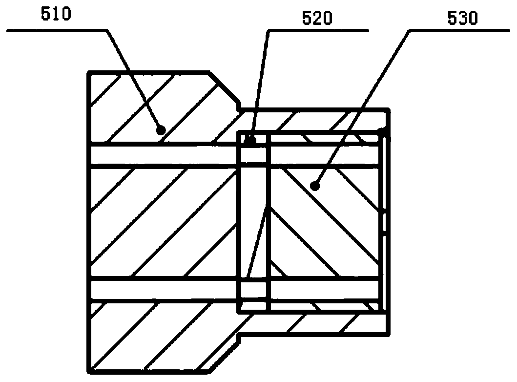
[0025] figure 2 A cross-sectional view of the specific structure of an embodiment of the wire transition catheter of the present invention is shown. The wire transfer conduit includes a main body 510 , a sealing gasket 520 and a compression block 530 . The outer wall of the main body is divided into a first section of the outer wall and a second section of the outer wall. The cross-sectional area of ​​the first section of the outer wall is larger than that of the second section of the outer wall, and a shoulder structure is formed at the junction of the two sections of the outer wall. The inside of the main body has a section of hollow cavi...


PUM


Abstract

The invention provides a wire transferring guide tube which is used for sealing connection between two mutually isolated cavities; the wire transferring guide tube comprises a main body, a sealing gasket and a pressing block, wherein the outer wall of the main body is divided into two sections in the connection direction of a first cavity and a second cavity; the section area of the outer wall ofthe first section is larger than that of the outer wall of the second section, so that a shaft shoulder structure is formed at the junction of the two sections of the outer wall; the main body is embedded in the connecting end wall of the first cavity, wherein one side of the main body is pressed and positioned through the connecting end wall of the second cavity, and the other side of the main body is blocked and positioned by the connecting end wall of the first cavity through the shaft shoulder structure; the inner part of the main body is provided with a section of hollow cavity structurein the connecting direction so as to accommodate the pressing block; the sealing gasket is arranged in the hollow cavity structure through the pressing block; and at least one channel is distributed in the connecting direction of the wire transferring guide tube so as to be used for interconnecting wires between the first cavity and the second cavity.

Description

technical field [0001] The invention relates to a wire transition conduit, in particular, a wire transition conduit with good sealing performance and easy replacement is designed. Background technique [0002] Electrical components such as electro-hydraulic servo valves and linear displacement sensors have a limited maximum operating temperature. When installed in environments beyond their normal operating temperature range, such as actuators and hydraulic mechanical devices, working fluids are required to cool the electrical components. . [0003] Generally, electrical components such as electro-hydraulic servo valves and linear displacement sensors are placed in electrical connectors with cooling cavities, such as figure 1 As shown, the electrical connector includes a socket portion 100 and a main body portion 200. The main body portion 200 is divided into a cooling cavity 210 and an air cavity 220, wherein the cooling cavity 210 is filled with a working fluid 211, and th...

Claims


Application Information

Patent Timeline
Patent Type & Authority Patents(China)
IPC IPC(8): H01R13/52
CPCH01R13/5202
Inventor 单亚杰
Owner AECC COMML AIRCRAFT ENGINE CO LTD
Why Eureka
Try Eureka