Granulator

A granulator and conveying mechanism technology, applied in the direction of mold extrusion granulation, etc., can solve the problems of material overflow, etc., and achieve the effect of easy observation, convenient feeding, and reduced installation height

Pending Publication Date: 2019-03-08
JIANGSU SANY ENVIRONMENTAL TECH LTD
View PDF2 Cites 13 Cited by
  • Summary
  • Abstract
  • Description
  • Claims
  • Application Information

AI Technical Summary

Problems solved by technology

The material 5 is poured down from above, and it is easy to cau

Method used


Image

  • Granulator
  • Granulator
  • Granulator

Examples


Embodiment 1

[0089] Embodiment 1, the structural form of the feeding device 100 is specifically described below:

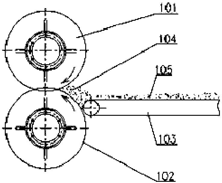
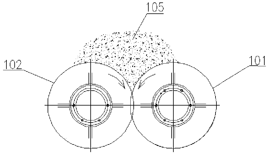
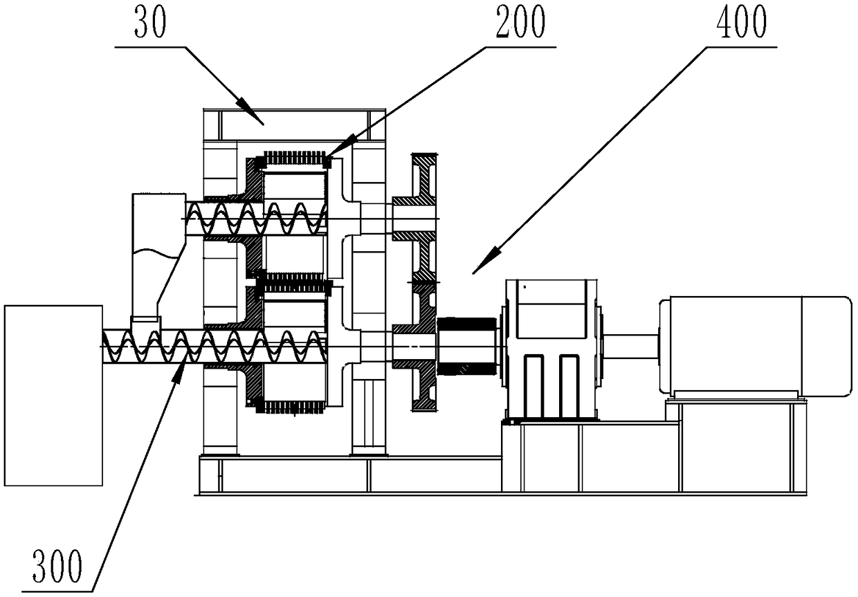
[0090] like Figure 4 and Figure 5 As shown, the granulator provided by the present invention includes the feeding device 100 including the conveying mechanism 101; the molding device 200 includes the upper hollow mold roll 01 and the lower hollow mold roll 02, and the upper hollow mold roll 01 and the lower The hollow mold rolls 02 mesh with each other and form the bell mouth feed area 102; the conveying mechanism 101 is in contact with the lower hollow mold roll 01 and forms a wrap angle with the lower hollow mold roll 01, so that The molded roller 01 and the conveying mechanism 101 co-extrude the flattened material to the bell mouth feeding area 102 .

[0091] It should be noted that, the upper hollow mold roll 101 and the lower hollow mold roll 102 may be placed opposite to each other in addition to being placed up and down.

[0092] In this embodiment, the material 10...

Embodiment 2

[0108] Embodiment 2, on the basis of Embodiment 1, specifically describe the structural form of the molding device 200:

[0109] After the feeding device feeds the raw material into the bell mouth feeding area formed by the meshing of the upper hollow die roll and the lower hollow die roll, the raw material is formed by the hollow die roll under the rolling action of the upper hollow die roll and the lower hollow die roll .

[0110] Specifically, the hollow roller includes a roller body (203) with a hollow cavity (202), and bosses (204) and grooves (205) are alternately arranged on the roller body (203), each boss (204) is respectively provided with protruding teeth (206), forms tooth groove (207) between the adjacent protruding teeth (206) on each boss (204), and groove (205) bottom passes through feed forming hole ( 208) communicates with said hollow cavity (202). During the forming process, a boss of one hollow mold roll is inserted into a groove of another hollow mold ro...

Embodiment 3

[0144] Embodiment 3, on the basis of Embodiment 1 and Embodiment 2, the structural form of the discharge device 300 is specifically described below:

[0145] like image 3 , Figure 19 - Figure 23 As shown, the granulator includes a discharge device 300, the discharge device 300 includes a hopper 301 and a discharge mechanism, the hopper is installed on the discharge mechanism and communicated with the discharge mechanism, the discharge The feeding mechanism is used to output materials; the material receiving hopper is provided with a material cutting piece, which is used to cut off the material when the material falls into the receiving hopper; a part of the discharging mechanism is located in the hollow mold In the roller, another part extends out of the hollow mold roller, and the receiving hopper is installed on the part of the discharge mechanism.

[0146] In this embodiment, the receiving hopper is located in the hollow cavity 202 of the hollow mold roll, and can cat...


PUM


Abstract

The invention discloses a granulator. The granulator comprises a feeding device, wherein the feeding device comprises an upper hollow die roll, a lower hollow die roll and a conveying mechanism; the upper hollow die roll and the lower hollow die roll are engaged with each other to form a bell-mouthed feeding region; and the conveying mechanism is in contact with the lower hollow die roll, and a wrap angle is formed between the conveying mechanism and the lower hollow die roll, so that a material which is flattened under co-extrusion of the lower hollow die roll and the conveying mechanism is conveyed to the bell-mouthed feeding region. The flattened material is uniformly and orderly conveyed to the bell-mouthed feeding region, and when the material is extruded, the conveying mechanism canfurther stop dropping of the material. The probability of clamping the material by the lower hollow die roll is increased, and therefore, the granule forming rate is increased. By a wrap angle type feeding mechanism, the mounting height of a feeding system can be reduced, and a feeding condition is convenient to observe.

Description

technical field [0001] The invention relates to the technical field of granule forming, in particular to a granulator. Background technique [0002] A large amount of straw is burned every year in our country, which not only causes serious pollution to the environment, but also wastes a lot of clean energy. [0003] The pellet machine can process high-density, high calorific value, and low-cost clean energy—biomass combustion pellets. As a new type of fuel, its unique advantages have won wide recognition. [0004] In the production process of biomass fuel pellets, the material needs to be conveyed to the bell mouth area of ​​the gear rings that mesh with each other in the pellet molding machine, and the materials are clamped by the teeth of the two ring gears and squeezed into the cavity for molding. [0005] Patent one ZL201610404703.X is adopted figure 1 The conveying mechanism 3 conveys the material 5 to the bell mouth feeding area 4 . The posture of the material 5 is...

Claims


Application Information

Patent Timeline
IPC IPC(8): B01J2/22
CPCB01J2/22
Inventor 匡苍豪李宁波李乃柱
Owner JIANGSU SANY ENVIRONMENTAL TECH LTD
Why Eureka
Try Eureka