Steel wire drawing and winding mechanism

A technology for a wire winding mechanism and a steel wire is applied in the field of wire drawing and winding mechanism, which can solve the problems of a single winding mechanism, unable to prevent the steel wire from being wound in one place, etc. Effect

Inactive Publication Date: 2019-03-08
王嘉政
View PDF5 Cites 4 Cited by
  • Summary
  • Abstract
  • Description
  • Claims
  • Application Information

AI Technical Summary

Problems solved by technology

[0002] Steel wire is one of the four types of steel plates, tubes, shapes, and wires. It is a reprocessed product made of hot-rolled wire rods through cold drawing. During its processing, it needs to be drawn and rolled. Now Some winding mechanisms are single, and it is impossible to flexibly adjust the distance between the fixed pillars according to the specifications of the pay-off rollers of different specifications, which reduces its practical range. Arranging the steel wires during the process cannot prevent the steel wires from being entangled in one place, which greatly reduces the processing efficiency of the steel wires

Method used


Image

  • Steel wire drawing and winding mechanism
  • Steel wire drawing and winding mechanism
  • Steel wire drawing and winding mechanism

Examples


Embodiment Construction

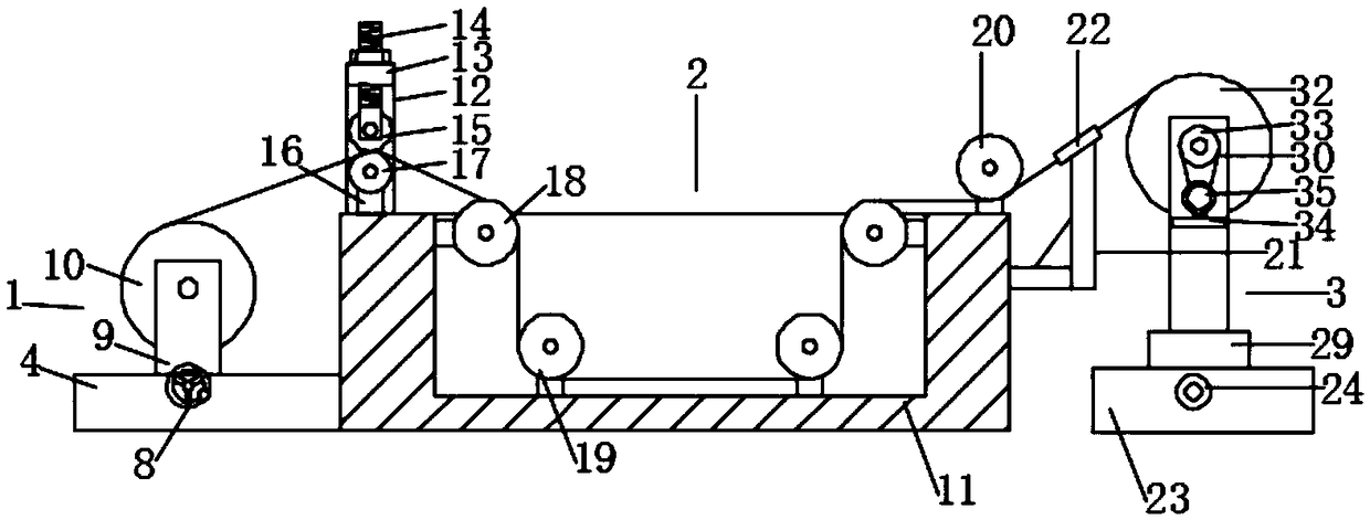
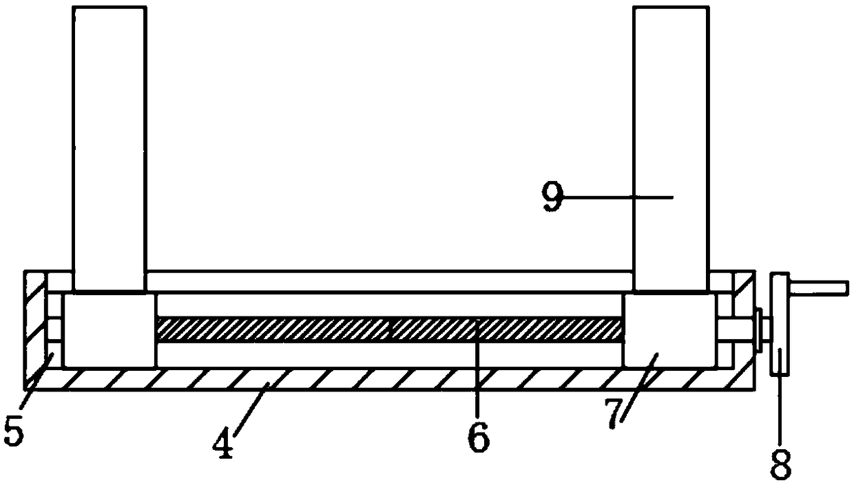
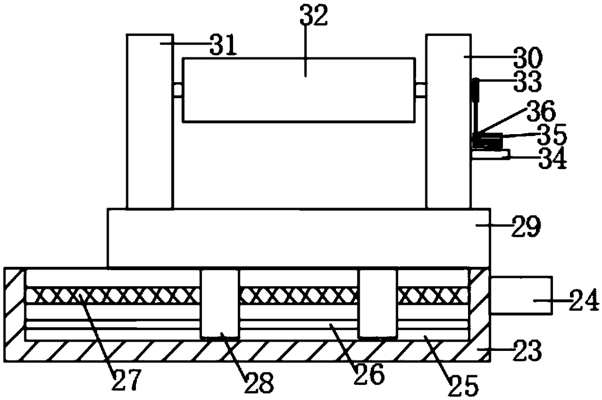
[0019] Such as Figure 1-3 As shown, this specific embodiment adopts the following technical solutions: a steel wire drawing and receiving mechanism, including a wire releasing mechanism 1, a drawing mechanism 2 and a wire receiving mechanism 3, and one side of the wire releasing mechanism 1 is provided with a drawing Mechanism 2, and the side of the drawing mechanism 2 away from the wire releasing mechanism 1 is provided with a wire receiving mechanism 3, and the wire releasing mechanism 1 is composed of a first fixed seat 4, a distance adjusting chute 5, a distance adjusting screw rod 6, The distance adjustment slider 7, the distance adjustment handwheel 8, the fixed pillar 9 and the pay-off roller 10 are composed of a distance adjustment chute 5 at the middle position of the top of the first fixed seat 4, and the distance adjustment chute 5 inner wall A distance-adjusting screw rod 6 is rotationally connected between the corresponding two sides, and the outside of the dista...


PUM


Abstract

The invention discloses a steel wire drawing and winding mechanism. The steel wire drawing and winding mechanism comprises a wire unwinding mechanism, a drawing mechanism and a wire winding mechanism,wherein one side of the wire unwinding mechanism is provided with the drawing mechanism, the side, away from the wire unwinding mechanism, of the drawing mechanism is provided with the wire winding mechanism, and the wire unwinding mechanism is composed of a first fixed seat, a distance adjusting sliding groove, a distance adjusting screw rod, distance adjusting sliding blocks, a distance adjusting hand wheel, fixed supporting columns and a wire unwinding roller. According to the steel wire drawing and winding mechanism, by means of the arrangements of the distance adjusting screw rod and thedistance adjusting hand wheel, the separation distance between the fixed supporting columns can be flexibly adjusted according to the wire unwinding rollers of different specifications, and the practicality range of the steel wire drawing and winding mechanism is broadened; by means of the arrangements of a first pressing wheel and a second pressing wheel, squeezing and drawing on steel wires arerealized; and the steel wires are winded through a wire winding roller, under the action of a reciprocating screw rod, the wire winding roller is made to perform reciprocating motions, arranging of the steel wires in the winding process is realized, the steel wires are prevented from being wound in one place, and the machining efficiency of the steel wires is greatly improved.

Description

Technical field: [0001] The invention relates to the field of wire collection mechanisms, in particular to a wire drawing and collection mechanism for steel wires. Background technique: [0002] Steel wire is one of the four types of steel plates, tubes, shapes, and wires. It is a reprocessed product made of hot-rolled wire rods through cold drawing. During its processing, it needs to be drawn and rolled. Now Some winding mechanisms are single, and it is impossible to flexibly adjust the distance between the fixed pillars according to the specifications of the pay-off rollers of different specifications, which reduces its practical range. Arranging the steel wires in the process cannot prevent the steel wires from being entangled in one place, which greatly reduces the processing efficiency of the steel wires. Invention content: [0003] The object of the present invention is to provide a steel wire drawing and collecting mechanism in order to solve the above problems, wh...

Claims


Application Information

Patent Timeline
Patent Type & Authority Applications(China)
IPC IPC(8): B21C1/02B21C9/00B21C47/04
CPCB21C1/02B21C9/00B21C47/04
Inventor 王嘉政
Owner 王嘉政
Why Eureka
Try Eureka