Eureka AIR delivers breakthrough ideas for toughest innovation challenges, trusted by R&D personnel around the world.

Flight ink droplet inspection device and method suitable for inkjet printing

An ink drop detection and ink jet printing technology, applied in printing and other directions, can solve the problem of no flying ink drop observation, etc., and achieve the effect of real and credible observation results, better observation results, and high volume calculation accuracy.

Active Publication Date: 2019-03-08
武汉国创科光电装备有限公司
View PDF5 Cites 23 Cited by
  • Summary
  • Abstract
  • Description
  • Claims
  • Application Information

AI Technical Summary

Benefits of technology

This patented solution improves upon previous methods used for observing flight inkdrops during imaging processes such as laser printers (LB). It allows us to measure various factors like particle sizes, speeds, pressure levels, injector angles, and positions along different axes simultaneously without compromising their reliability over conventional techniques. Additionally, it introduces an algorithm called space fractions computation, where we design a 3D model of each drop's area instead of just one dimension. By analyzing these models, we aim to improve image quality while reducing variations caused by imperfections within the process itself. Overall, our new approach enhances the performance capabilities of LB systems and provides accurate measurements of inks spray patterns.

Problems solved by technology

The present problem addressed in this patents relates to improving image quality during electronic displays (FPD) production processes due to factors like uneven surface shapes caused by injector systems. Current methods require manual adjustments based upon visual inspections, making them difficult to measure accurately at different angles while still maintain consistency across devices. This requires an improved system capable of measuring various parameters simultaneously without requiring human intervention.

Method used


Image

  • Flight ink droplet inspection device and method suitable for inkjet printing
  • Flight ink droplet inspection device and method suitable for inkjet printing
  • Flight ink droplet inspection device and method suitable for inkjet printing

Examples


Embodiment Construction

[0038] In order to make the object, technical solution and advantages of the present invention clearer, the present invention will be further described in detail below in conjunction with the accompanying drawings and embodiments. It should be understood that the specific embodiments described here are only used to explain the present invention, not to limit the present invention. In addition, the technical features involved in the various embodiments of the present invention described below can be combined with each other as long as they do not constitute a conflict with each other.

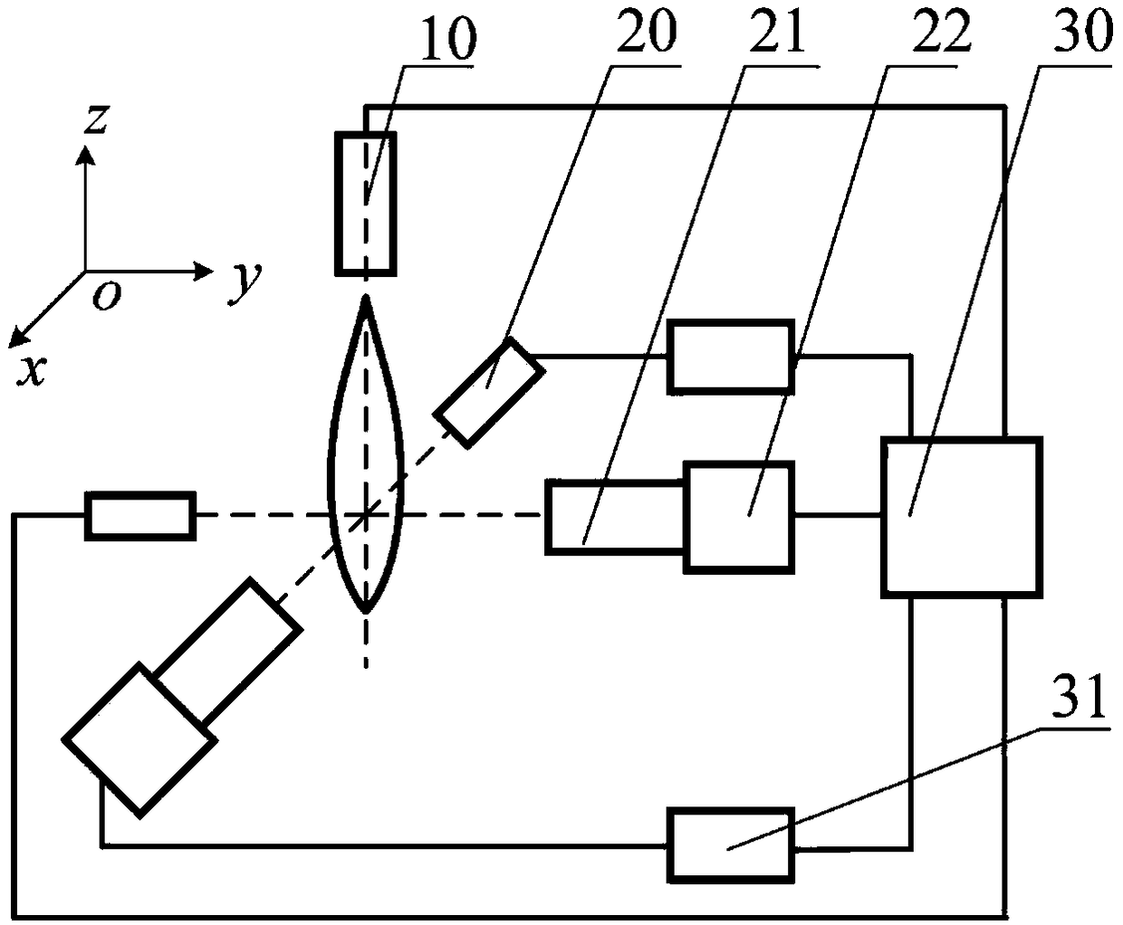
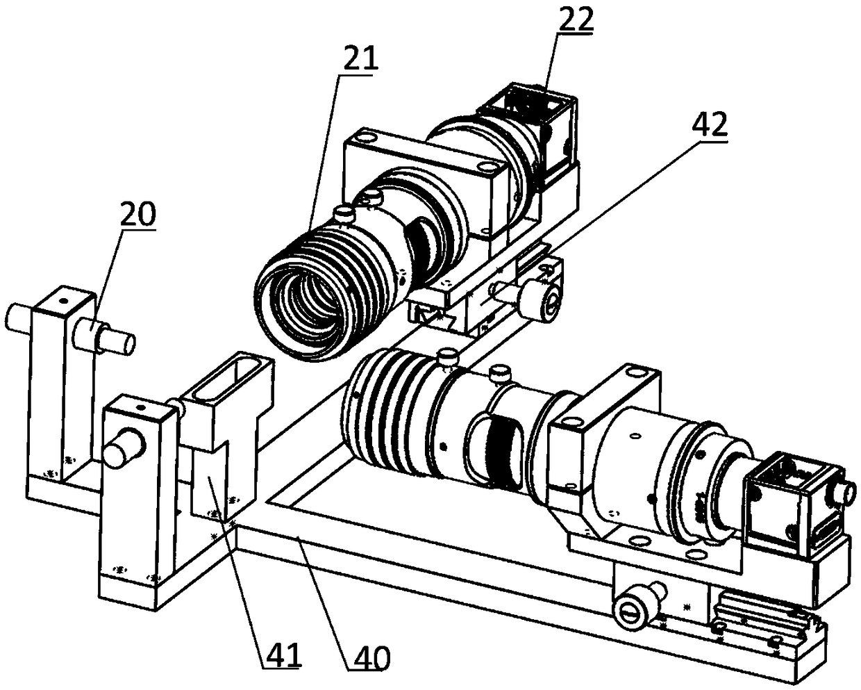
[0039] figure 1 It is a schematic diagram of the overall structure of the flying ink drop detection device constructed according to the present invention. Such as figure 1 As shown, the flying ink drop detection device mainly includes components such as a vision module, a control module, and a mechanical auxiliary module, which will be explained in detail below.

[0040] As one of the key imp...


PUM


Abstract

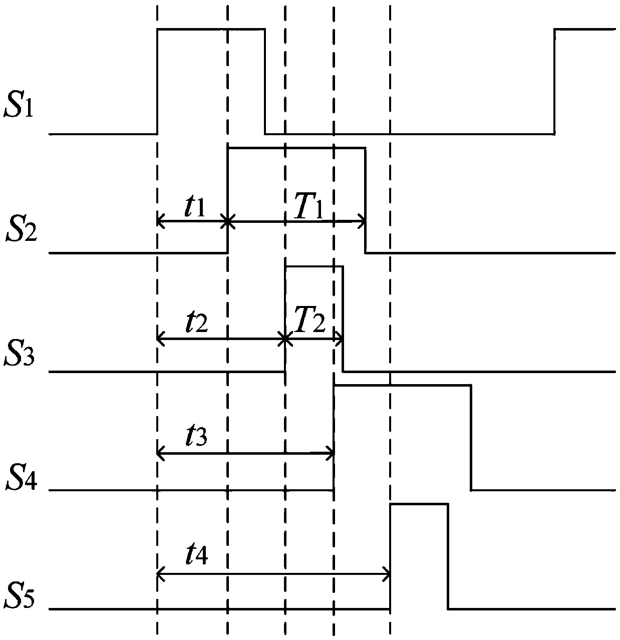
The invention belongs to the technical field of inkjet printing visual inspection, and discloses a flight ink droplet inspection device suitable for inkjet printing. The flight ink droplet inspectiondevice comprises a visual module, a control module and a mechanical auxiliary module; the visual module comprises two cameras, a lens and a stroboscopic light source, and the directions of the two cameras are perpendicular; the control module comprises a main controller used for controlling trigger signal timing sequences of two sets of visual hardware, and two light source controllers; and the mechanical auxiliary module comprises a rack, a fine-tuning mechanism and an ink liquid collecting device. The invention further discloses a corresponding inspection method and an optimization algorithminvolving multiple inspection parameters. Through the flight ink droplet inspection device, the multiple parameters of flight ink droplets can be measured multi-directionally, the drop point positionis estimated, measurement is more accurate, and high-frequency jet observation and array flight ink droplet inspection can be achieved.

Description


Claims


Application Information

Patent Timeline
Owner 武汉国创科光电装备有限公司
Why Eureka
Eureka Blog
Learn More