Charging pile special for ships

A technology for charging piles and ships, which is applied in charging stations, electric vehicle charging technology, electric vehicles, etc., to achieve the effect of worry-free operation and convenient application

Pending Publication Date: 2019-03-08
GUANGZHOU XUANTONG JIENENG TECH CO LTD
View PDF0 Cites 6 Cited by
  • Summary
  • Abstract
  • Description
  • Claims
  • Application Information

AI Technical Summary

Problems solved by technology

[0003] The purpose of the present invention is to provide a special charging pile for ships on water in order to solve the above-mentioned problems in the charging of existing ships

Method used


Image

  • Charging pile special for ships
  • Charging pile special for ships
  • Charging pile special for ships

Examples


Embodiment 1

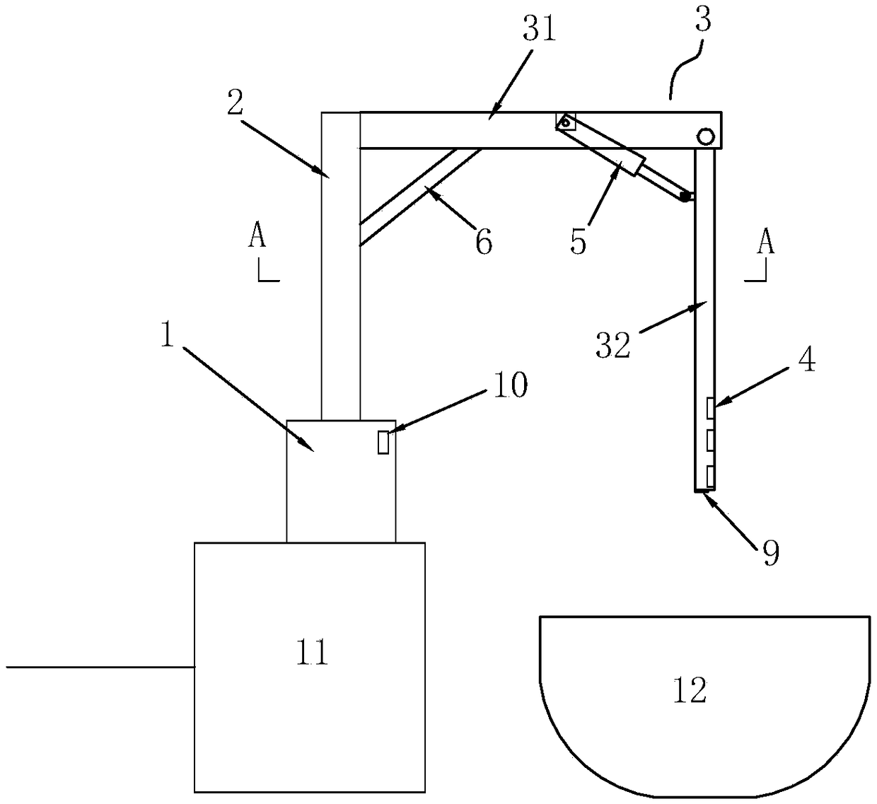
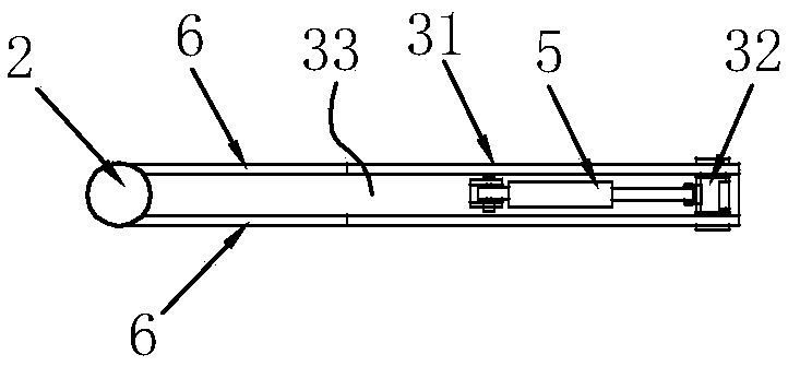
[0031] refer to figure 1 with figure 2 The special charging pile for water ships shown includes an electric pile base 1, a column 2, a charging arm 3 and a charging socket 4. The electric pile base 1 is a fixed body of a column 2, and the column 2 is a hollow body. There is also a control circuit inside the electric pile base 1 or the column 2, the electric pile base 1 fixes the column 2 at a designated position, the charging arm 3 is composed of a cross arm 31 and a swing arm 32, the cross arm 31 One end is fixedly installed on the column 2, and the other end is rotationally connected with the swing arm 3. The charging socket 4 is arranged on the swing arm 32, and the control circuit is used to control the charging function of the charging pile.

[0032] In the embodiment, the control circuit includes conventional technologies such as an IC circuit, a display screen, and function buttons, and the power line of the control circuit is embedded in the electric pile base 1 , th...

Embodiment 2

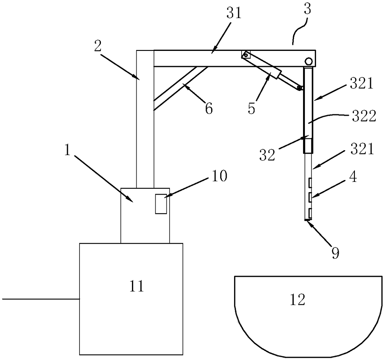
[0036] refer to Figure 4 As shown, the technical characteristics of this embodiment are: the swing arm 32 is composed of a multi-section telescopic arm 321, and the multi-section telescopic arm 321 is provided with a push-pull rod 322. Under the action of the push-pull rod 322, the swing arm 32 forms a telescopic Structure, the push-pull rod 322 is a hydraulic push rod, and the rest are the same as the above embodiment.

[0037] When this embodiment is applied, the multi-segment telescopic arm 321 is a plurality of elongated tubes with multiple sizes nested in each other, and a push-pull rod 322 is arranged inside the tube, and the push-pull rod 322 drives the small tube to expand and contract in the large tube to form a telescopic function, that is, multi-segment telescopic The arm 321 controls the telescopic movement of the multi-section telescopic arm 321 through the push-pull rod 322, thereby adjusting the length of the swing arm 32, that is, adjusting the distance from t...

Embodiment 3

[0039] refer to Figure 4 As shown, the technical feature of this embodiment is: the column 2 is rotatably installed on the electric pile base 1 . Specifically, the column 2 is installed on the electric pile base 1 through two bearings 7, and the two bearings 7 allow the column 2 to be rotatably installed on the electric pile base 1, such as an installation on the electric pile base 1. The fixed inner cavity of the column 2, the upper and lower ends of the inner cavity are respectively provided with a circular notch for installing the bearing 7, the bearing 7 is fixedly installed at the position of the circular notch, and the column 2 is installed on the electric pile base 1 through the rotation of the bearing 7 superior. In order to avoid the winding problem of the power line of the charging pile when the column 2 rotates, an electric slip ring 8 is provided at the docking position between the column 2 and the electric pile base 1, and the electric slip ring 8 is located bet...


PUM


Abstract

The invention relates to a charging pile special for ships. The charging pile includes an electric pile base (1), a stand column (2), a charging arm (3) and a charging socket (4). The electric pile base (1) is a fixed body of the stand column (2), and the stand column (2) is a hollow body. A control circuit is arranged in the electric pile base (1) or the stand column (2). The electric pile base (1) makes the stand column (2) fixed at a designated position, the charging arm (3) is composed of a cross arm (31) and a swing arm (32), one end of the cross arm (31) is fixedly installed on the standcolumn (2), the other end of the cross arm (31) is rotatably connected with the swing arm (33), the charging socket (4) is arranged on the swing arm (3), and the circuit board is used for controllingthe charging function of the charging pile. When in use, the charging position is adjusted by the swing position of the swing arm, so as to avoid the problems that overlong charging cables need to bemanually pulled when the ship stops for charging, much labor is consumed and the efficiency is low. The charging pile is more convenient to use, and operation is easy and saves more labor.

Description

technical field [0001] The invention relates to a charging device, in particular to a charging pile for an electric ship. Background technique [0002] When the electric boat needs to be charged, it needs to berth at the set berth and connect the cable for charging operation. This charging method requires manual cable connection, so the operation intensity is high and the efficiency is low, and the long-term dragging of the cable is very difficult. It is susceptible to wear and tear, which will affect the quality and affect the charging function. Contents of the invention [0003] The object of the present invention is to provide a special charging pile for ships on water in order to solve the above-mentioned problems existing in the charging of existing ships. [0004] The object of the invention can be realized through the following technical solutions: [0005] Special charging piles for ships on water, including electric pile bases, columns, charging arms and chargin...

Claims


Application Information

Patent Timeline
Patent Type & Authority Applications(China)
IPC IPC(8): B60L53/31B60L53/14B60L53/35
CPCB60L2200/32Y02T10/70Y02T10/7072Y02T90/12Y02T90/14
Inventor 成志雄
Owner GUANGZHOU XUANTONG JIENENG TECH CO LTD
Why Eureka
Try Eureka