
Braiding machine

A technology of braiding machine and vibrating machine, which is applied in the field of braiding machines, can solve the problems of unsatisfactory feeding effect and no automatic feeding device for braiding machines, and achieve better feeding effect and easy disassembly

Inactive Publication Date: 2019-03-08
广州市七研精密仪器有限公司
View PDF0 Cites 0 Cited by
  • Summary
  • Abstract
  • Description
  • Claims
  • Application Information

AI Technical Summary

Problems solved by technology

[0003] However, the existing braiding machine does not have a suitable automatic feeding device, and the feeding effect is not ideal by using manual feeding or electric feeding.

Method used

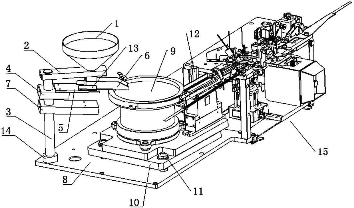
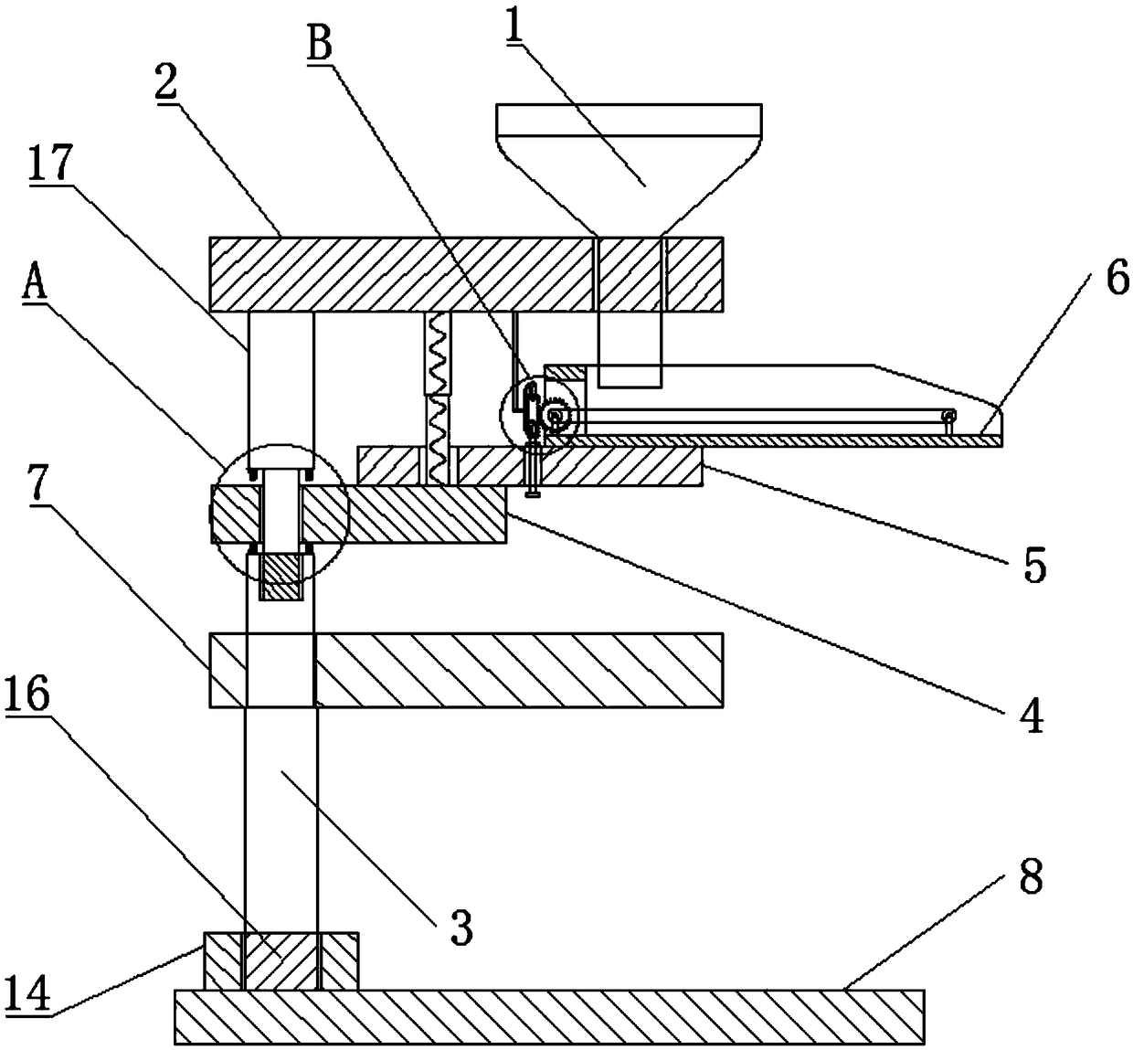
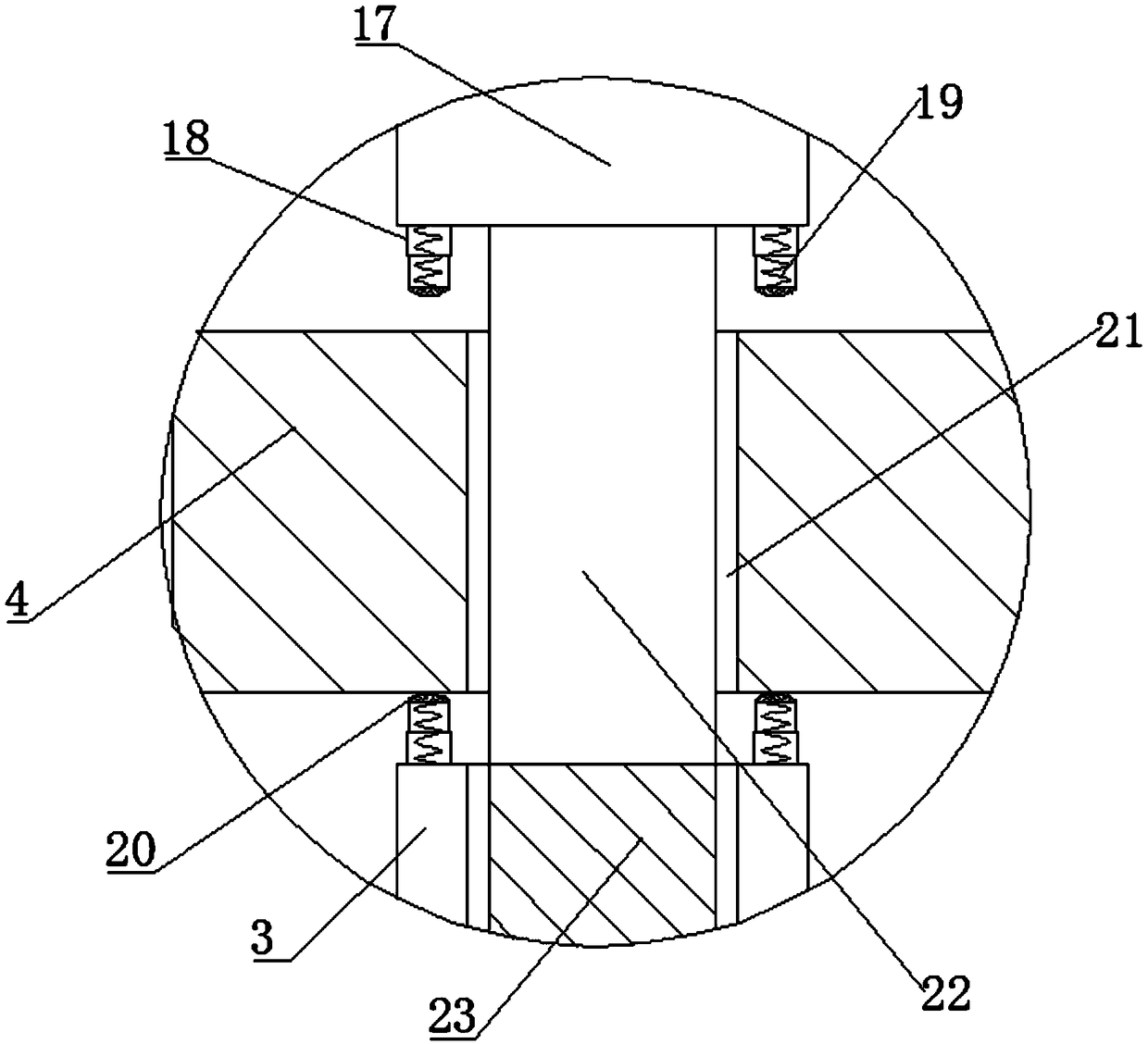

Image

  • Braiding machine
  • Braiding machine
  • Braiding machine

Examples


Embodiment Construction

[0028] The preferred embodiments of the present invention will be described in detail below in conjunction with the accompanying drawings, so that the advantages and features of the present invention can be more easily understood by those skilled in the art, so as to define the protection scope of the present invention more clearly.

[0029] refer to Figure 1-5As shown, the present invention provides a kind of braiding machine, comprises feeding device, and described feeding device comprises funnel 1 and blanking funnel 6, and blanking funnel 6 is installed in the lower end of funnel 1, and the left end of blanking funnel 6 is provided with blanking The funnel through hole 32, the lower end of the funnel 1 is provided with a funnel fixing plate 2, the funnel fixing plate 2 is provided with a threaded socket, the lower end of the funnel 1 runs through the threaded through hole and extends to the lower side of the funnel fixing plate 2, and the bottom of the funnel 1 The lower ...


PUM


Abstract

The invention relates to the field of braiding machines and discloses a braiding machine. The braiding machine comprises a funnel and a blanking funnel. The blanking funnel is arranged at the lower end of the funnel. A blanking funnel through hole is formed in the left end of the blanking funnel. A funnel fixing plate is arranged at the lower end of the funnel. A threaded inserting hole is formedin the funnel fixing plate. The lower end of the funnel penetrates through a threaded through hole and extends to the lower side of the funnel fixing plate. The lower end of the funnel is in threadedconnection with the threaded through hole. A second funnel support rod is fixedly connected to the lower end of the funnel fixing plate. The second funnel support rod is located at the side far away from the funnel. The lower end of the second funnel support rod is fixedly connected with a vibrating inserting rod. The vibrating inserting rod penetrates through a first vibrating through hole and issleeved with a funnel direct vibration fixing block, and the lower end of the vibrating inserting rod is fixedly connected with a screw rod, so that automatic feeding can be realized, manual operation or electric drive is not required in the feeding process, and the feeding effect is better.

Description

technical field [0001] The present invention relates to the field of braiding machines, more specifically, to a braiding machine. Background technique [0002] Taping machines can be divided into two categories: semi-automatic and fully automatic. They put bulk component products into the carrier tape after passing through inspection, reversing, and testing stations. With the continuous upgrading, refinement and high integration of electronic products, electronic components have also been converted from plug-in type to patch type to save the installation space of the circuit board and expand the function of the product. It is a large-scale revolution in the electronics industry. The braiding machine will vibrate during operation, and the vibration potential energy has not been properly utilized. [0003] But existing braiding machine does not have suitable automatic feeding device, adopts the mode of manual feeding or electric feeding, and feeding effect is unsatisfactory. ...

Claims


Application Information

Patent Timeline
IPC IPC(8): B65B35/02B65B15/04
CPCB65B35/02B65B15/04
Inventor 袁就成
Owner 广州市七研精密仪器有限公司
Learn More