
Spiral high-birefringence-structure elliptic-polarization-maintaining optical fiber manufacturing process

A technology with high birefringence and elliptical polarization, which is applied in the direction of manufacturing tools, glass manufacturing equipment, glass fiber products, etc., can solve the problems of limited continuous drawing length and unstable drawing of elliptically polarized optical fiber

Inactive Publication Date: 2019-03-08
上海康阔光智能技术有限公司
View PDF2 Cites 1 Cited by
  • Summary
  • Abstract
  • Description
  • Claims
  • Application Information

AI Technical Summary

Problems solved by technology

[0006] The technical problem to be solved by the present invention is to provide a helical high birefringence structure elliptic polarization-preserving optical fiber manufacturing process, which can solve the problem of unstable drawing of elliptic polarization-preserving optical fiber in the prior art and the problem of limited continuous drawing length

Method used


Image

  • Spiral high-birefringence-structure elliptic-polarization-maintaining optical fiber manufacturing process
  • Spiral high-birefringence-structure elliptic-polarization-maintaining optical fiber manufacturing process
  • Spiral high-birefringence-structure elliptic-polarization-maintaining optical fiber manufacturing process

Examples


no. 1 example

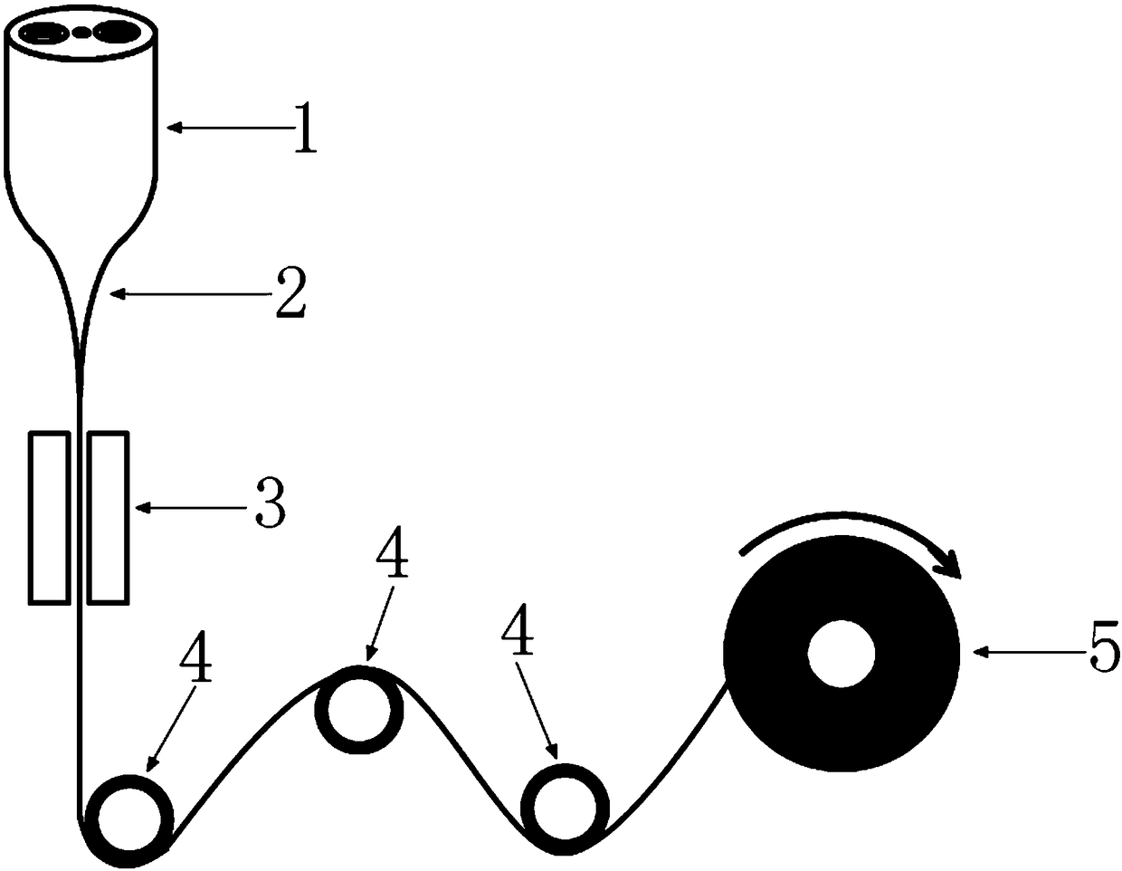
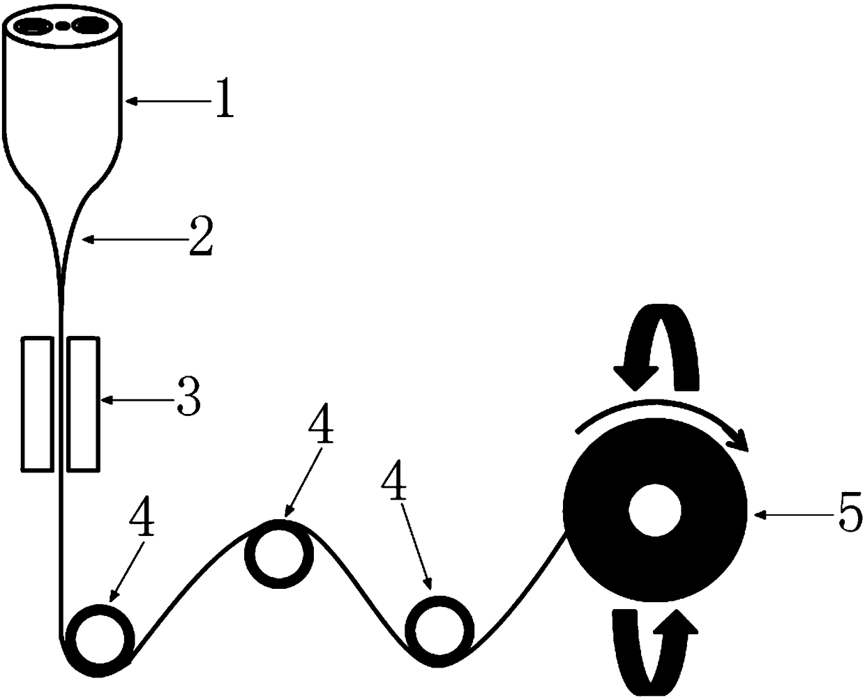
[0020] The manufacturing process of the helical high birefringence structure elliptic polarization-preserving optical fiber provided by this embodiment, such as image 3 As shown, the lower end of the optical fiber preform 1 is heated in the high-temperature heating zone 2, and is drawn into a bare optical fiber with a diameter meeting the requirements. The surface of the bare optical fiber is coated with a layer of coating material in the optical fiber coating zone 3, and then Guided by the fiber guide wheel 4, it winds on the receiving reel 5 at last.

[0021] In the above drawing process, such as image 3 As shown, the optical fiber preform 1 does not rotate, and during the drawing process, the take-up reel 5 not only rotates around its axis of rotation, but also flips at a high speed. Vertical, so that the drawn optical fiber produces torsion, and this torsion can easily overcome the friction of the fiber guide wheel 4 (the fiber guide wheel 4 can have multiple in the wir...

no. 2 example

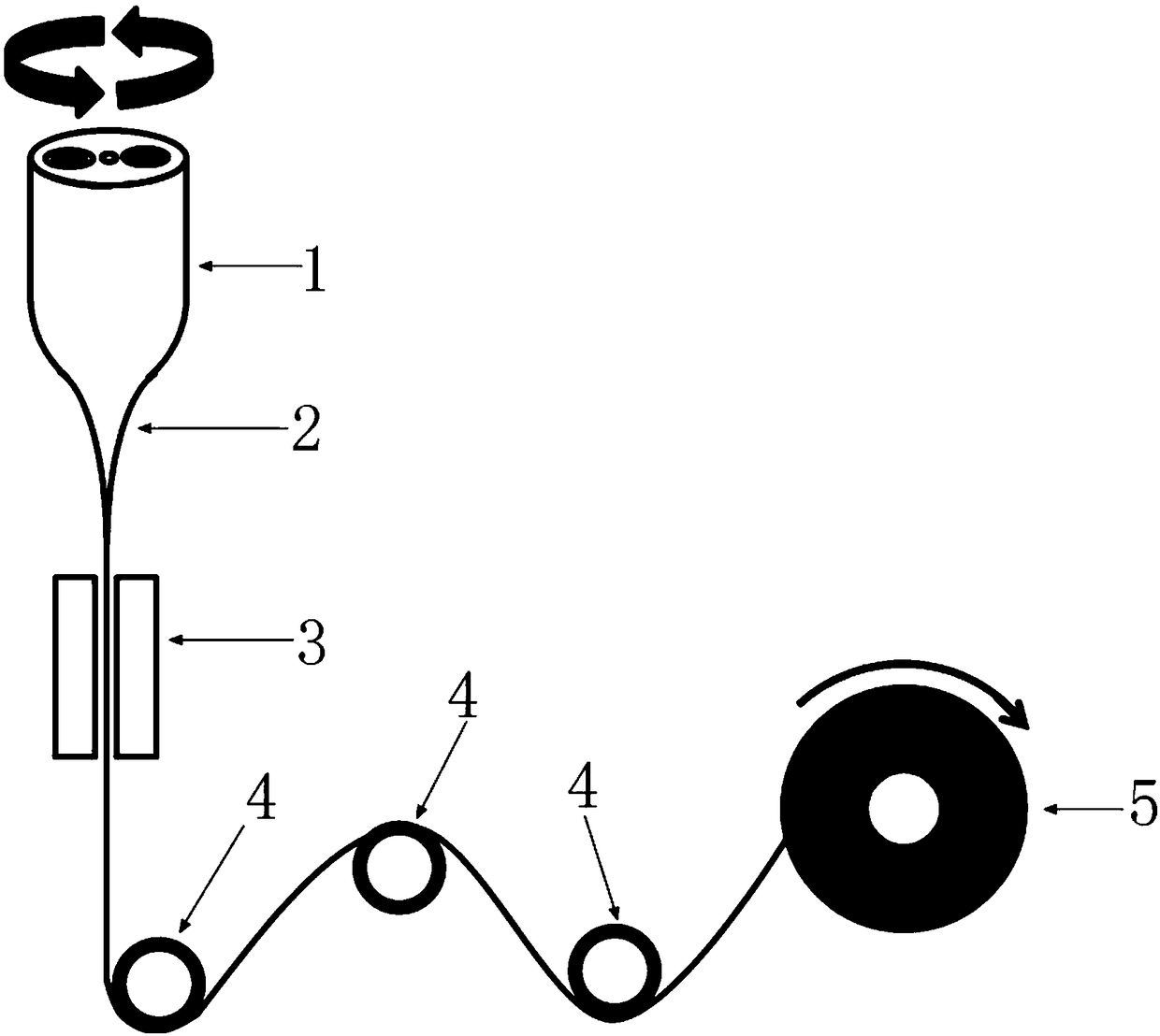
[0029] The manufacturing process of the helical high birefringence structure elliptic polarization-preserving optical fiber provided by this embodiment, such as Figure 4 As shown, the difference from the first embodiment is that the optical fiber preform 1 is changed to a rotating state, and the lower end of the optical fiber preform 1 is heated in the high-temperature heating zone 2, and is drawn into a bare optical fiber with a diameter that meets the requirements. A layer of coating material is coated in the optical fiber coating area 3 , then guided by the optical fiber guide wheel 4 , and finally wound on the take-up reel 5 . The reel 5 rotates around its shaft while turning over at high speed. The central axis of the reel 5 overturned is perpendicular to the axis of rotation of the reel 5 , and the direction of rotation of the optical fiber preform 1 is in line with the The twist direction of the optical fiber generated by flipping is opposite, so that the twist of the ...


PUM


Abstract

The invention discloses a spiral high-birefringence-structure elliptic-polarization-maintaining optical fiber manufacturing process. During the wire drawing process, an optical fiber perform is in a non-rotating state or a rotating state, and a wire winding plate is turned over during the wire drawing, so that a drawn optical fiber produces a twisting force, and the twisting force is transmitted to a high-temperature heating area, so that the optical fiber forms an inherent spiral high birefringence structure in the area; the problem of instability of wire drawing in the traditional process issolved, the long-distance stability of the optical fiber feature is ensured, and the true industrialization of optical fiber manufacturing is ensured.

Description

technical field [0001] The invention relates to an optical fiber manufacturing process, and specifically belongs to a helical high birefringence structure elliptic polarization-preserving optical fiber manufacturing process. Background technique [0002] The helical high birefringence structure ellipse-preserving fiber (referred to as ellipse-preserving fiber) is the core material of the optical fiber current sensor based on the optical Faraday effect. Similar, such as panda type, bow tie type, oval cladding type, oval core type, one-line type, etc. [0003] From the structural point of view, the biggest difference between the elliptic polarization-maintaining fiber and the linear polarization-maintaining fiber is that the line birefringence orientation in the linear polarization-maintaining fiber is constant or changes very slowly with the transmission distance (or fiber axis) , this slow change is caused by the fiber drawing process, it is not deliberately made like this,...

Claims


Application Information

Patent Timeline
IPC IPC(8): C03B37/025
CPCC03B37/025C03B2203/30C03B2205/06
Inventor 黄勇
Owner 上海康阔光智能技术有限公司
Learn More