LCD device and electronic apparatus

A technology of liquid crystal display device and liquid crystal layer, which can be applied to static indicators, optics, instruments, etc., and can solve problems such as insufficient brightness of transmission display

Inactive Publication Date: 2004-06-09
BOE TECH GRP CO LTD
View PDF4 Cites 11 Cited by
  • Summary
  • Abstract
  • Description
  • Claims
  • Application Information

AI Technical Summary

Problems solved by technology

[0009] First of all, in order to solve the problem of insufficient brightness of the transmissive display in the above-mentioned transflective liquid crystal display device, the inventor considered Figure 8 A liquid crystal display device with the configuration shown

Method used


Image

  • LCD device and electronic apparatus
  • LCD device and electronic apparatus
  • LCD device and electronic apparatus

Examples


no. 1 Embodiment approach

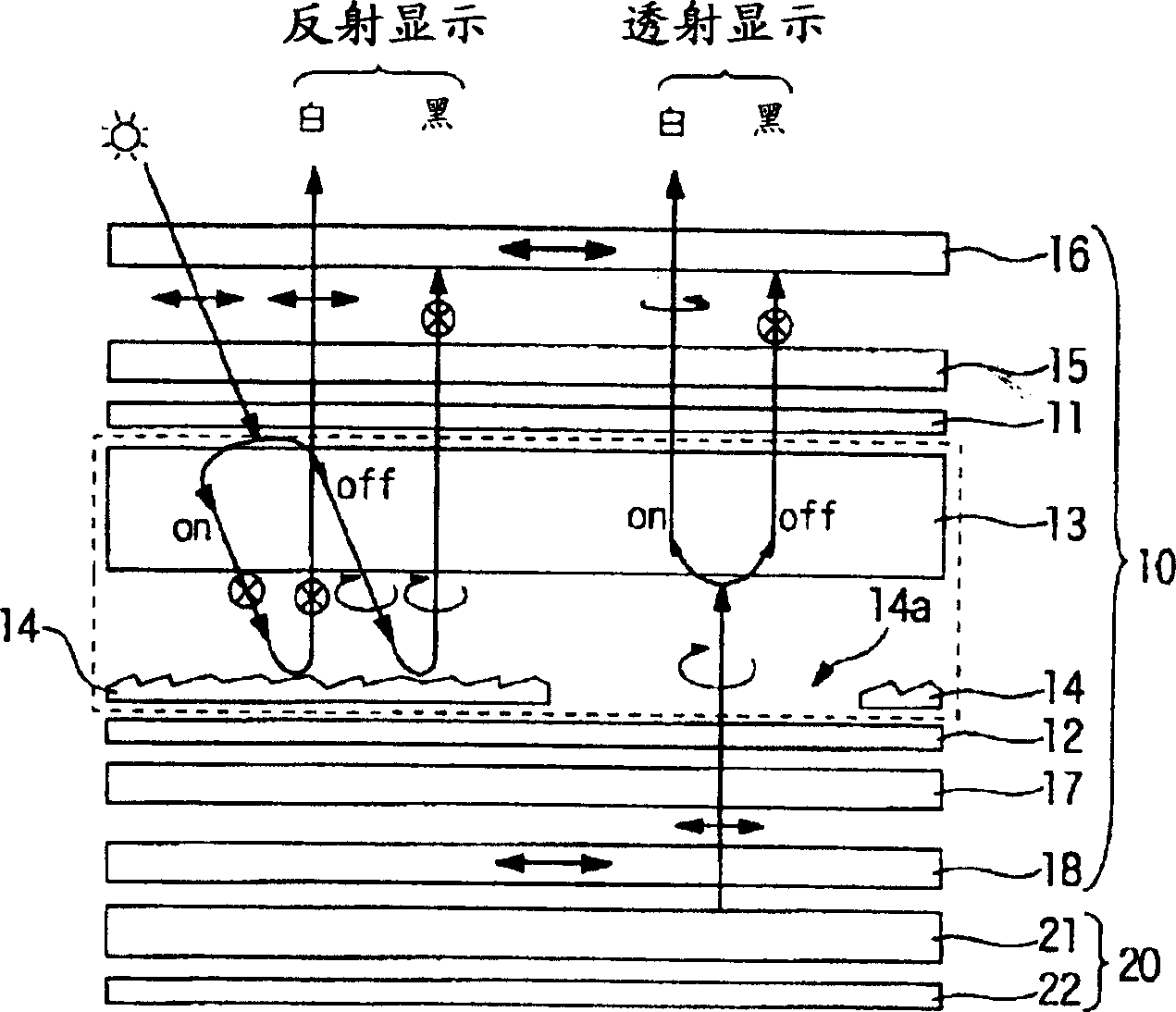
[0059] figure 1 It is an explanatory view showing the cross-sectional structure and display principle of the liquid crystal display device according to the first embodiment of the present invention. figure 1 The illustrated liquid crystal display device is a transflective liquid crystal display device including a liquid crystal panel 10 and a backlight (illumination device) 20 arranged on the back side (lower side in the figure) of the liquid crystal display device.

[0060] The liquid crystal panel 10 sandwiches the liquid crystal layer 13 between the upper substrate 11 and the lower substrate 12 arranged oppositely; on the outer side of the upper substrate 11, an upper retardation plate (upper retardation layer) 15 and an upper polarizing plate are laminated in sequence. 16. On the outer side of the lower substrate 12, a lower retardation plate (lower retardation layer) 17 and a lower polarizing plate 18 are laminated. On the liquid crystal layer 13 side of the lower subs...

no. 2 Embodiment approach

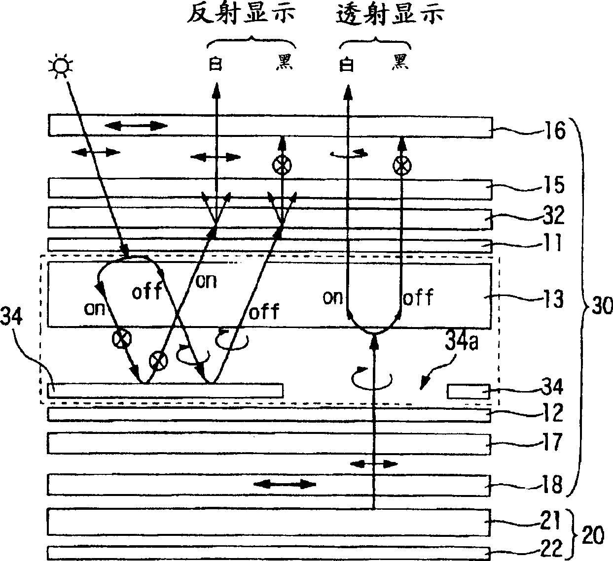
[0077] Next, refer to figure 2 A second embodiment of the present invention will be described. figure 2 The illustrated liquid crystal display device is a transflective liquid crystal display device including a liquid crystal panel 30 and a backlight (illumination device) 20 arranged on the back side (lower side in the figure) of the liquid crystal display device.

[0078] The liquid crystal panel 30 sandwiches the liquid crystal layer 13 between the upper substrate 11 and the lower substrate 12 arranged oppositely, and on the outer side of the upper substrate 11, an off-axis anisotropic light scattering layer 32 and an upper retardation plate 15 are sequentially stacked. and an upper polarizing plate 16 , and a lower retardation plate 17 and a lower polarizing plate 18 are stacked on the outer side of the lower substrate 12 . On the liquid crystal layer 13 side of the lower substrate 12, a reflective layer 34 is partially formed in the dot region. In addition, on the liqu...

no. 3 Embodiment approach

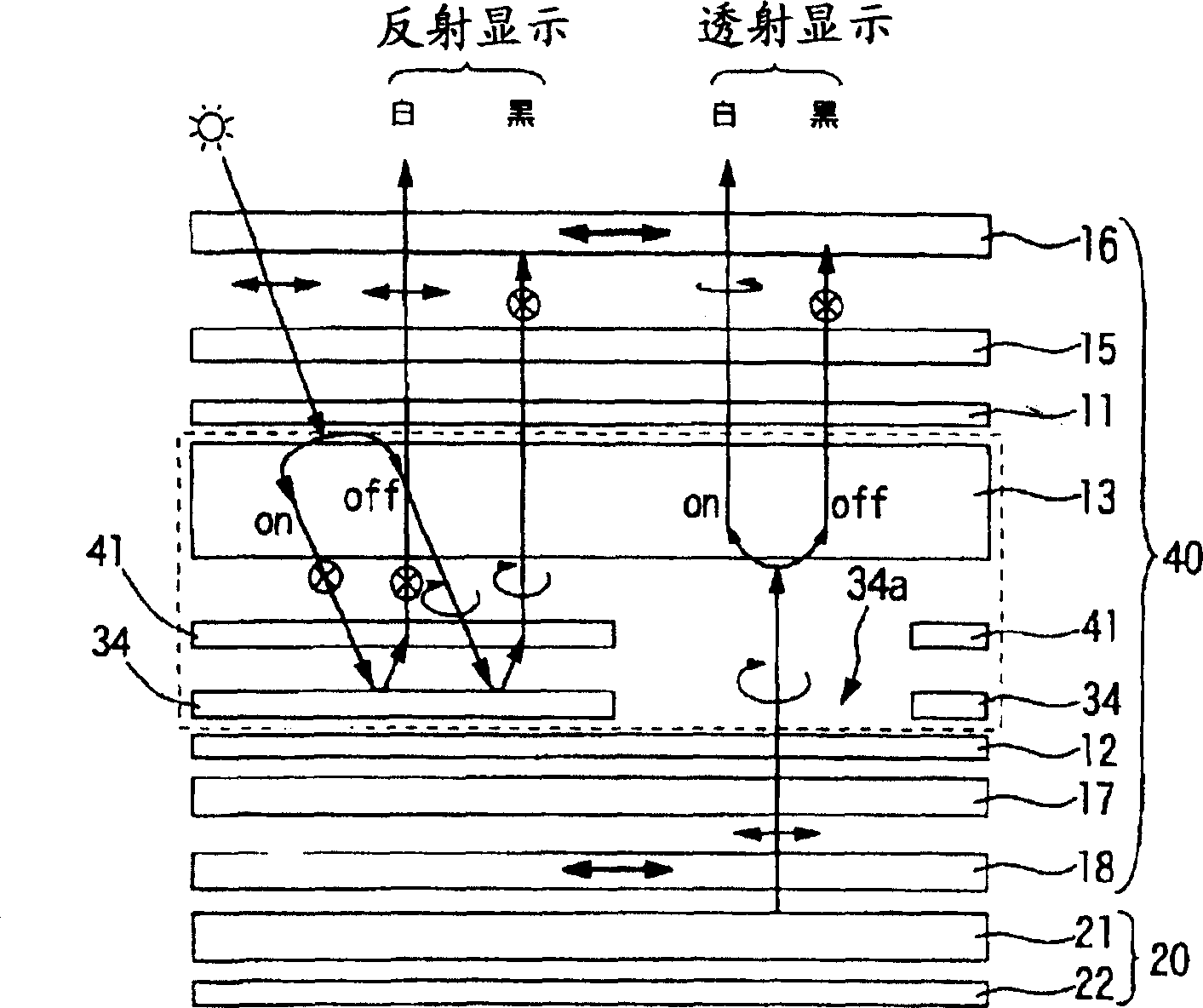
[0094] Next, refer to image 3 A third embodiment of the present invention will be described. image 3 The illustrated liquid crystal display device is a transflective liquid crystal display device including a liquid crystal panel 40 and a backlight (illumination device) 20 arranged on the back side (lower side in the figure) of the liquid crystal display device.

[0095] The liquid crystal panel 40 sandwiches the liquid crystal layer 13 between the upper substrate 11 and the lower substrate 12 which are arranged oppositely. A lower retardation plate 17 and a lower polarizing plate 18 are stacked on the outer side of the polarizer. On the side of the liquid crystal layer 13 of the lower substrate 12, a reflective layer 34 is partially formed in the dot region of the liquid crystal panel 40, and a forward transmission rear diffractive layer (anisotropic optical layer) 41 is provided on the plane region of the reflective layer 34. . In addition, on the liquid crystal layer 13...


PUM


Abstract

The invention provides a transflective liquid crystal display device which provides both high-contrast, bright reflective and transmissive displays. The liquid crystal display device of the present invention can include a liquid crystal panel and a backlight. The liquid crystal panel includes a liquid crystal layer, which is disposed between an upper substrate and a lower substrate and whose liquid crystals are disposed in a twisted manner at an angle in the range of from 220 to 270 degrees, an upper retardation film and a lower retardation film, which are disposed above and below the liquid crystal layer so as to sandwich it; an upper polarizer 16 and a lower polarizer, which are disposed on the outer surfaces of their respective retardation films, and a sloping reflective layer. Light impinging upon the upper polarizer from the liquid crystal layer is elliptically polarized light. The product of an optical anisotropy Deltan of the liquid crystal layer and thickness d of the liquid crystal layer, Deltand, lies in the range of from 820 nm to 950 nm. Light obliquely impinging upon the liquid crystal panel exits in a direction that is closer to a direction perpendicular to the liquid crystal panel than to a specular reflection direction.

Description

technical field [0001] The invention relates to a liquid crystal display device and electronic equipment. Background technique [0002] A semi-transmissive (transmissive) reflective liquid crystal display device is a liquid crystal display device that uses external light in a bright place like a normal reflective liquid crystal display device, and can see the display state clearly with the help of an internal light source in a dark place. Such a liquid crystal display device is disclosed, for example, in (Patent Document 1). Figure 10 It is an explanatory diagram for explaining the schematic configuration and display principle of the transflective liquid crystal display device. [0003] Figure 10 Among them, the liquid crystal display device 100 is composed of a liquid crystal panel 110 and a backlight 120 . The liquid crystal panel 100 is from the display surface side (the upper side of the drawing), and the upper polarizing plate 116, the first upper retardation plate 1...

Claims


Application Information

Patent Timeline
Patent Type & Authority Applications(China)
IPC IPC(8): G02F1/133G02F1/1335G02F1/13363G02F1/139
CPCG02F1/13363G02F1/133555G02F1/1397G02F1/1335
Inventor 饭岛千代明
Owner BOE TECH GRP CO LTD
Why Eureka
Try Eureka