Liquid crystal display device and electronic device
a display device and liquid crystal technology, applied in liquid crystal compositions, instruments, chemistry apparatus and processes, etc., can solve the problems of insufficient luminance and contrast of the transmittance display, and achieve the effect of effectively preventing a reduction in contrast and tone reversal, effective preventing a reduction in display quality, and marked
- Summary
- Abstract
- Description
- Claims
- Application Information
AI Technical Summary
Benefits of technology
Problems solved by technology
Method used
Image
Examples
first embodiment
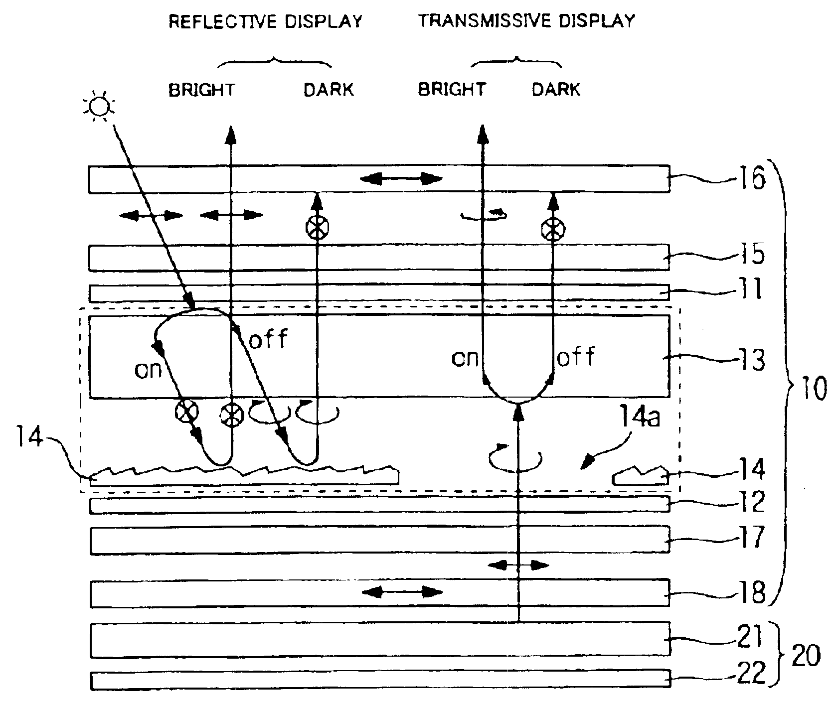
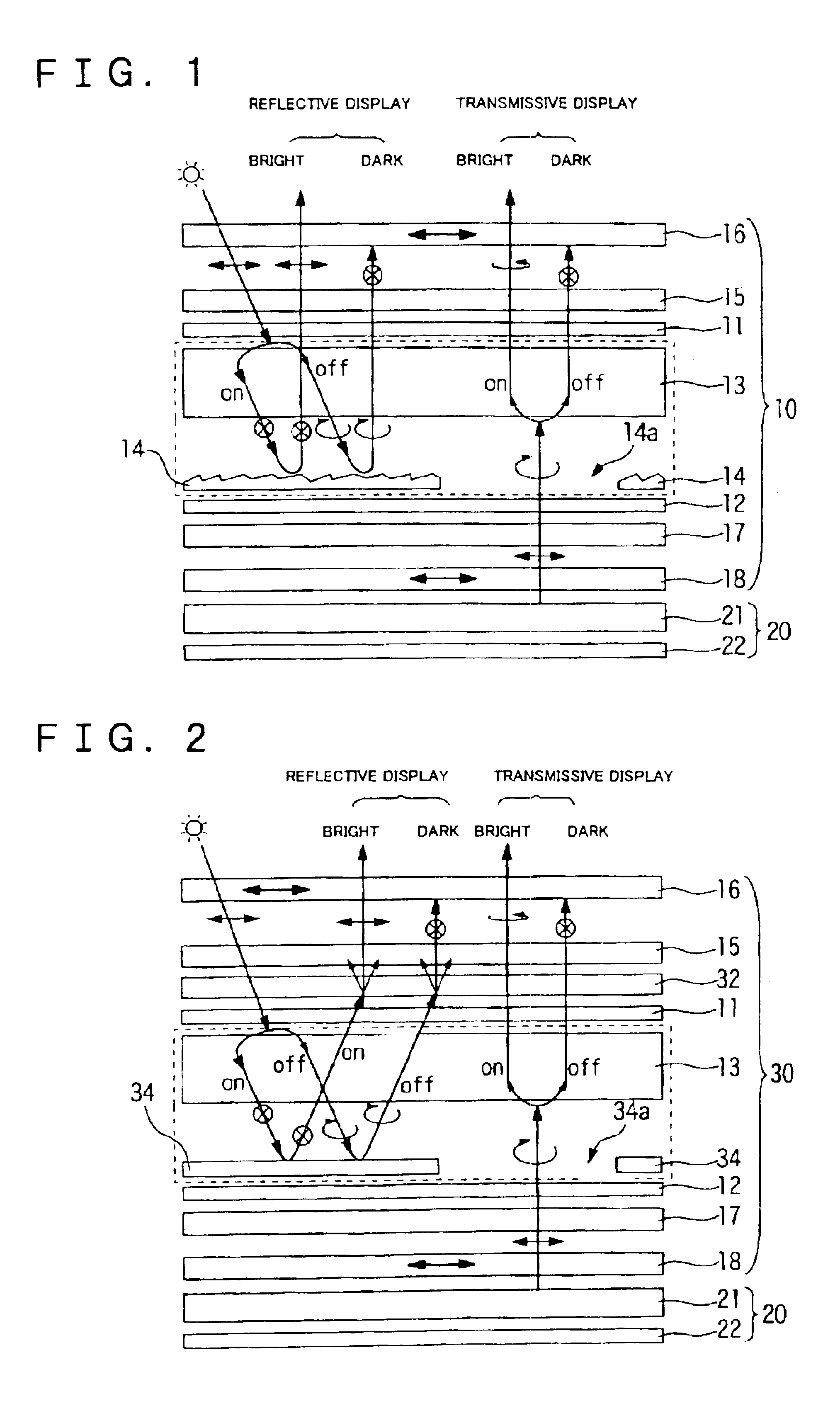
[0054]FIG. 1 illustrates the structure of a liquid crystal display device of the present invention in cross section and display principles thereof. The liquid crystal display device shown in FIG. 1 is a transflective liquid crystal display device that can include a liquid crystal panel 10 and a backlight (illuminating device) 20, disposed at the back side (bottom side in FIG. 1) of the liquid crystal panel 10.
[0055]In the liquid crystal panel 10, a liquid crystal layer 13 is sandwiched between opposing upper and lower substrates 11 and 12, an upper retardation film (upper retardation layer) 15 and an upper polarizer 16 are stacked in that order upon the outer surface of the upper substrate 11, and a lower retardation film (lower retardation layer) 17 and a lower polarizer 18 are stacked upon the outer surface of the lower substrate 12. At the liquid-crystal-layer-13 side of the lower substrate 12, a sloping reflective layer 14 is formed partly within a dot area, and functions as a t...
second embodiment
[0071]Next, a description of the present invention will be given with reference to FIG. 2. A liquid crystal display device shown in FIG. 2 is a transflective liquid crystal display device comprising a liquid crystal panel 30 and a backlight (illuminating device) 20, disposed at the back side (bottom side in FIG. 2) of the liquid crystal panel 30.
[0072]In the liquid crystal panel 30, a liquid crystal layer 13 is sandwiched between opposing upper and lower substrates 11 and 12, an off-axis anisotropic light scattering layer 32, an upper retardation film 15, and an upper polarizer 16 are stacked in that order upon the outer surface of the upper substrate 11, and a lower retardation film 17 and a lower polarizer 18 are stacked upon the outer surface of the lower substrate 12. At the liquid-crystal-layer-13 side of the lower substrate 12, a reflective layer 34 is formed partly within a dot area. At the liquid-crystal-layer-13 side of the upper substrate 11 and the lower substrate 12, alt...
third embodiment
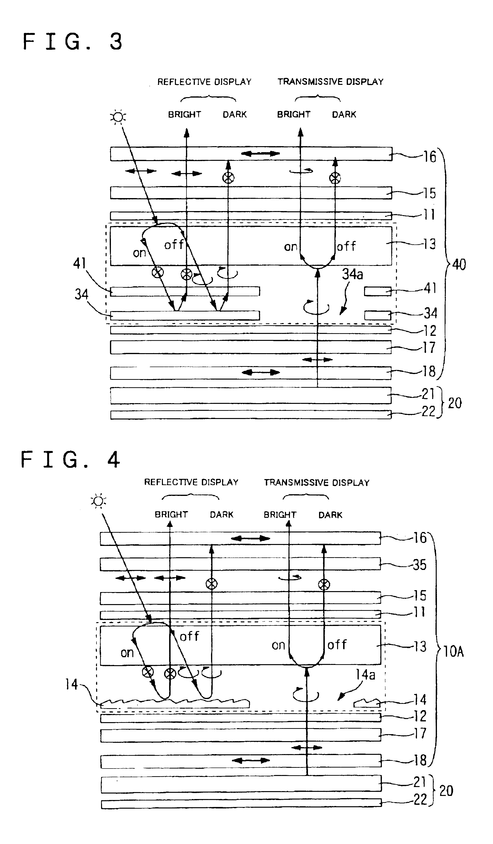
[0086]Next, a description of the present invention will be given with reference to FIG. 3. A liquid crystal display device shown in FIG. 3 is a transflective liquid crystal display device comprising a liquid crystal panel 40 and a backlight (illuminating device) 20, disposed at the back side (bottom side in FIG. 3) of the liquid crystal panel 40.
[0087]In the liquid crystal panel 40, a liquid crystal layer 13 is sandwiched between opposing upper and lower substrates 11 and 12, an upper retardation film 15 and an upper polarizer 16 are stacked in that order upon the outer surface of the upper substrate 11, and a lower retardation film 17 and a lower polarizer 18 are stacked upon the outer surface of the lower substrate 12. At the liquid-crystal-layer-13 side of the lower substrate 12, a reflective layer 34 is formed partly within a dot area, and a front-transmission, rear-diffraction layer (an anisotropic optical layer) 41 is disposed above a plane area of the reflective layer 34. At ...
PUM
 Abstract
Description
Claims
Application Information
 - R&D
- Intellectual Property
- Life Sciences
- Materials
- Tech Scout
- Unparalleled Data Quality
- Higher Quality Content
- 60% Fewer Hallucinations
Browse by: Latest US Patents, China's latest patents, Technical Efficacy Thesaurus, Application Domain, Technology Topic, Popular Technical Reports.
© 2025 PatSnap. All rights reserved.Legal|Privacy policy|Modern Slavery Act Transparency Statement|Sitemap|About US| Contact US: help@patsnap.com


