Gas transmission method of natural gas terminal station

A natural gas and station technology, which is used in gas/liquid distribution and storage, pipeline systems, mechanical equipment, etc., can solve the problems of low automation level of natural gas stations and cannot ensure the safety of gas use by downstream users, and reduce the risk of tripping , the effect of shortening response time, improving safety and reliability

Active Publication Date: 2019-03-08
浙江浙能天然气运行有限公司 +1
View PDF9 Cites 0 Cited by
  • Summary
  • Abstract
  • Description
  • Claims
  • Application Information

AI Technical Summary

Problems solved by technology

[0004] The technical problem to be solved and the technical task proposed by the present invention are to overcome the low level of automation of existing natural gas stations, which cannot guarantee the safety of gas consumption for downstream users, especially the faulty gas supply branch in the filtering area and metering area cannot quickly respond to make branch switching In order to solve the problem that the gas supply branch is shut off due to the action, the present invention proposes a gas transmission method for a natural gas station. The gas transmission method is suitable for the gas supply branch of the metering area and the filtering area, and can be based on the valve on the gas supply branch , The status of the transmitter automatically judges whether to switch the gas supply branch, so as to shorten the reaction time required for the switching action of the gas supply branch, improve the safety and reliability of the operation of the natural gas pipeline network, and the gas supply branch in the filter area of ​​the existing station The pipeline has a filter, and the gas supply branch of the metering area has a flow meter

Method used


Image

  • Gas transmission method of natural gas terminal station
  • Gas transmission method of natural gas terminal station
  • Gas transmission method of natural gas terminal station

Examples


Embodiment Construction

[0044] The present invention will be further described below in conjunction with the accompanying drawings and specific embodiments.

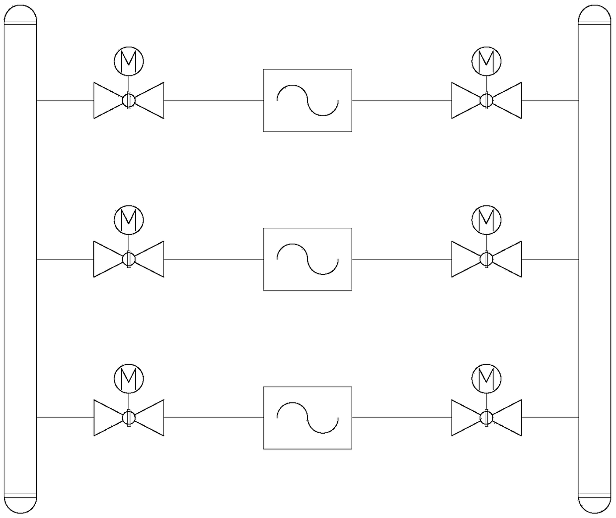
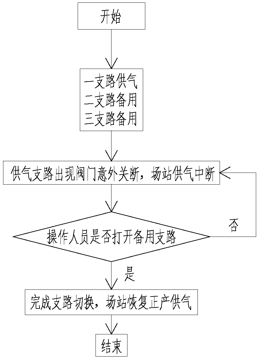
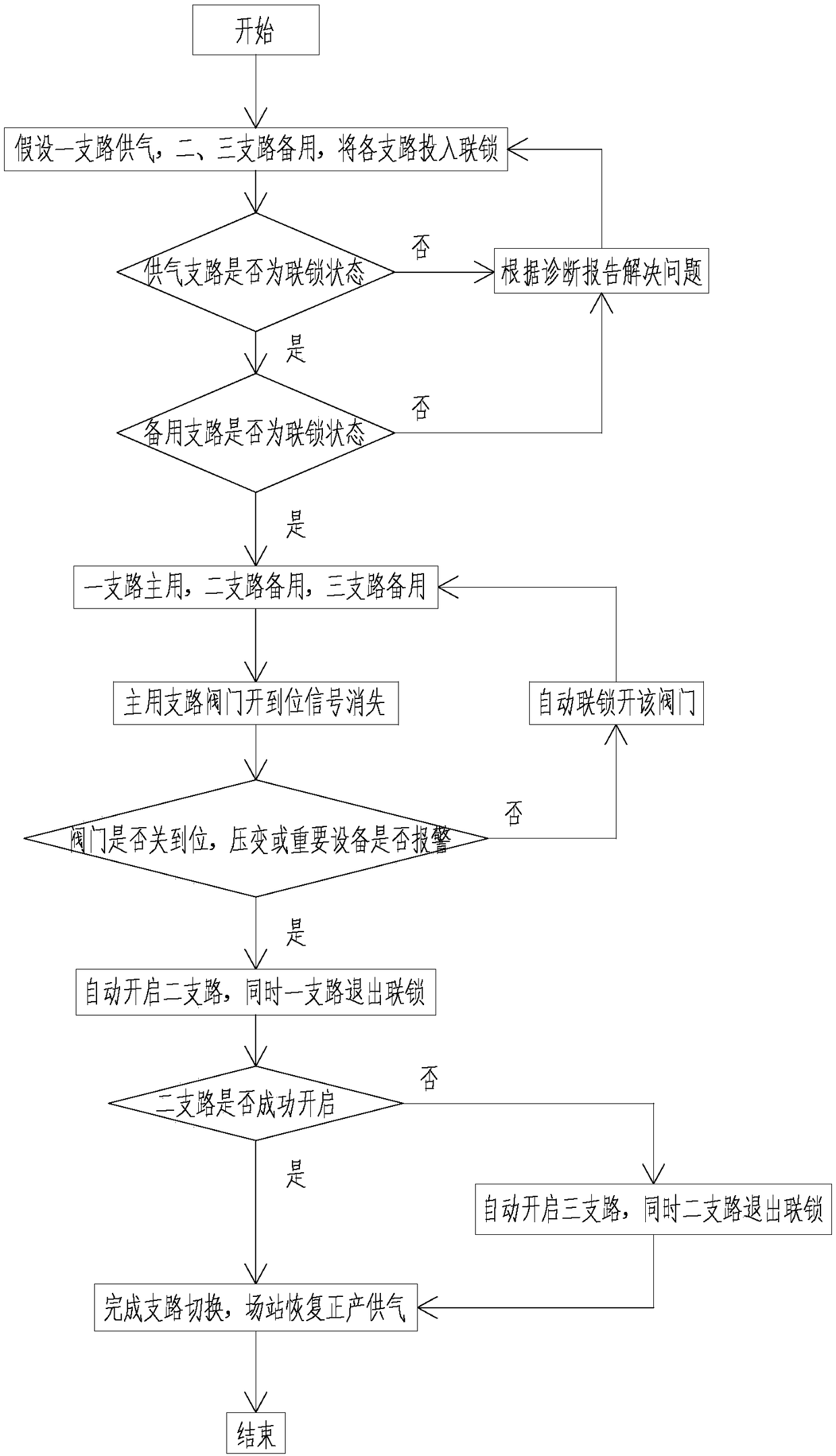
[0045] A natural gas field station gas transmission method, comprising the following steps carried out in sequence:

[0046] (1) Turn on the working mode

[0047] Put each air supply branch of the filter area and the metering area into interlock mode or free mode, the interlock mode indicates that the branch participates in redundancy, and the free mode indicates that the branch does not participate in redundancy and does not generate Any alarm; put each gas supply branch into the interlock mode under the condition of non-maintenance. The interlock mode is divided into two states: main or standby. Under the interlock mode, the branch with gas supply conditions is the main state. In the interlock mode, the branches that do not have the gas supply conditions are in the standby state; when the interlock mode is put into the main state or the stan...


PUM


Abstract

The invention relates to the technical field of natural gas transmission, in particular to a gas transmission method of a natural gas terminal station. The gas transmission method is suitable for gastransmission controlling of gas supplying branch of a terminal station filtering area and a metering area. The automatic level of an existing natural gas terminal station is low, and the gas safety ofdownstream users cannot be guaranteed, especially the filtering area and the the metering area are brokendown and the gas supplying branch cannot quickly respond to switch branch so as to cause the air supplying branch to be switched off. According to the gas transmission method of the natural gas terminal station, the method is based on self-diagnosis, the gas transmission reliability of the natural gas station is improved; particularly, the health condition of the interlocking air supplying branch is diagnosed in real time, on the basis of the states of the valves and transmitters on the gas supplying branch automatically judging whether the gas supply branch is switched or not; the reaction time required by the branch switching action after the air supplying branch is switched off is effectively shortened, the redundancy level of the natural gas station filter and the metering branch is further improved, and the safety and reliability of running of the natural gas pipe network areimproved.

Description

technical field [0001] The invention relates to the technical field of natural gas transportation, in particular to a natural gas field station gas transportation method, which is suitable for the gas supply branch of the field station filtering area and metering area. Background technique [0002] At present, the automation level of domestic natural gas stations is generally not high, and some provinces still rely on manual gas supply. In some provinces with advanced gas supply technology, the natural gas pipeline network adopts the SCADA system (Supervisory Control And Data Acquisition) for remote data collection and process station monitoring, and each station adopts the Station Control System (Station Control System) with PLC (Programmable Logic Controller) as the core ), complete the data collection and monitoring tasks of the process in the station, and transmit the operation status and various parameters of the process equipment to the dispatch control center in the p...

Claims


Application Information

Patent Timeline
Patent Type & Authority Applications(China)
IPC IPC(8): F17D1/02F17D3/01F17D5/00
CPCF17D1/02F17D3/01F17D5/005
Inventor 谭汉周东辉沈国良胡伯勇陆陆韩峰钟文晶何郁晟陆豪强
Owner 浙江浙能天然气运行有限公司
Why Eureka
Try Eureka