
Position locking device for drawer-type automatic change-over electric appliance

A technology of automatic conversion and locking device, applied in the direction of circuits, electrical switches, electrical components, etc., can solve the problems of unstable rotation of the rotating shaft, many fault points, instability, etc., to eliminate hidden dangers, avoid position movement, structure compact effect

Pending Publication Date: 2019-03-08
WUXI HANKWANG ELECTRIC
View PDF0 Cites 0 Cited by
  • Summary
  • Abstract
  • Description
  • Claims
  • Application Information

AI Technical Summary

Problems solved by technology

This kind of position locking device has the following problems: 1) Using gear transmission, the product body cannot complete the position movement due to jamming caused by uneven meshing between the gears; 2) In extreme cases, the gears will collapse and the entire transmission system will fail. Stop the transmission; 3) Due to the instability of the locking device itself and the many fault points, the rotation of the rotating shaft of the full gear at each stage is unstable, resulting in the connecting rod on the rotating shaft of a certain stage of full gear. If it deviates from the correct position, the product body cannot reach the correct locking position, which will bring difficulties to the operators and commissioning and maintenance personnel; 4), the use of gears for position transmission also increases the manufacturing cost of the switch

Method used


Image

  • Position locking device for drawer-type automatic change-over electric appliance
  • Position locking device for drawer-type automatic change-over electric appliance
  • Position locking device for drawer-type automatic change-over electric appliance

Examples


Embodiment 1

[0019] Embodiment 1: the sliding guide rail 9 slides to the left, and is locked in the off, test, and on positions in sequence;

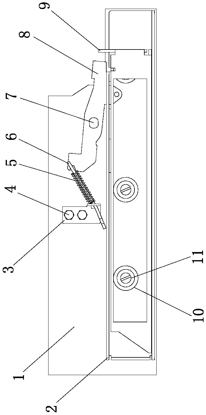
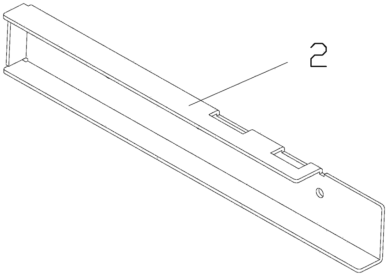
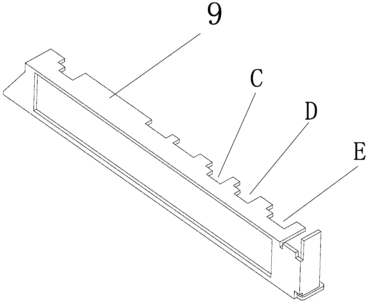
[0020] Such as Figure 1~6 As shown: In order to make the position locking device accurately lock the position of the product body in the drawer seat, the present invention includes a mounting plate 1, and the mounting plate 1 is provided with a nut 4 to fix the fixing plate 3 on the mounting plate 1 The first fixed shaft 7 passes through the corresponding hole on the lock 8, and the lock 8 is fixed on the mounting plate 1, but the lock 8 can flexibly rotate around the first fixed shaft 7; the connecting rod 6 is put on the spring 5, and then Pass one end of the connecting rod 6 through the corresponding hole of the fixing plate 3, compress the spring 5, and bite and lock the end of the connecting rod 6 with the U-shaped groove and the end of the lock 8 with the U-shaped groove; the first fixed shaft 7 passes through The corresponding holes on the ...

Embodiment 2

[0022] Embodiment 2: the sliding guide rail 9 slides to the right, and is locked in the connected, test and disconnected positions in sequence;

[0023] Such as Figure 1~6 , as shown: in order to make the position locking device accurately lock the position of the product body in the drawer seat, the present invention includes a mounting plate 1, on which a fixing plate 3 is arranged, fixed by screws and nuts 4. The lock catch 8 is fixed on the first fixed shaft 7 on the mounting plate 1, and the lock catch can rotate freely around the first fixed shaft 7; the spring 5 and the connecting rod 6 installed between the fixed plate 3 and the lock catch 8; Guide rail 2, fix the fixed guide rail 2 and the roller shaft 10 on the second fixed shaft 11 on the mounting plate 1, the roller shaft 10 can rotate freely around the second fixed shaft 11, the sliding guide rail 9 is installed in the fixed guide rail 2, and the sliding guide rail 9 There is a lock catch 8 on which one end fall...


PUM


Abstract

The invention relates to a position locking device for a drawer-type automatic change-over electric appliance. The locking device adopts a nut to fix a fixed board on a mounting plate; a first fixed shaft passes through a corresponding hole on a latch to fix the latch on the mounting plate; a connection rod is sleeved with a spring, and one end of the connection rod, at which a U-shaped groove isformed, is engaged and clamped with one end of the latch, at which a U-shaped groove is formed; a second fixed shaft passes through corresponding holes on a roller and a fixed guide rail to fix the roller and the fixed guide rail on the mounting plate so as to ensure that a sliding guide rail can slide in the fixed guide rail; and the sliding guide rail is placed in the fixed guide rail, and an upper attaching veneer of the sliding guide rail is attached to the roller. The position locking device is compact and reasonable in structure; and few parts are adopted, the connection rod is adopted to drive, the structure is simple, a locked position is supplied with a retention force by the spring so as to avoid position movement, a position of a product body in a drawer seat can be reflected inreal time, and a real locked position state of the automatic change-over switching electric appliance is provided for debugging overhaul personnel so as to avoid the insecurity hidden danger.

Description

technical field [0001] The invention relates to a position locking device of a drawer-type automatic switching electric appliance, which belongs to the technical field of automatic switching electric appliances. Background technique [0002] With the development of social economy, automatic transfer switch appliances are widely used in low-voltage power distribution systems in the fields of construction, fire protection, industry, communication, finance, transportation, military, etc., as a conversion between two power sources to ensure that important loads are not Intermittent power supply or allow short-term power outage for maintenance, debugging and overhaul. This requires the product to be very convenient and safe for maintenance, debugging, and overhaul to ensure the continuity of power consumption and the safety of equipment maintenance personnel. This device is a new type of position locking device designed and developed for drawer-type products. In the field of low...

Claims


Application Information

Patent Timeline
IPC IPC(8): H01H9/20
CPCH01H9/20
Inventor 杨海军吴晓亚管柯韩俊贤
Owner WUXI HANKWANG ELECTRIC
Learn More