Cooking appliance

A technology for cooking utensils and cooking chambers, which is applied in the direction of pressure cookers, etc., can solve the problems of high manufacturing cost, poor versatility, and large differences in the structure of the rice cooker's air extraction device, and achieve the effects of easy combination and installation, easy promotion and popularization, and improved versatility

Active Publication Date: 2019-03-12
FOSHAN SHUNDE MIDEA ELECTRICAL HEATING APPLIANCES MFG CO LTD
View PDF17 Cites 7 Cited by
  • Summary
  • Abstract
  • Description
  • Claims
  • Application Information

AI Technical Summary

Problems solved by technology

[0002] At present, the air extraction device of the vacuum rice cooker is mainly integrated in the upper cover of the rice cooker. The structure of the air extraction device of different rice cookers is quite different, and there is no stand

Method used


Image

  • Cooking appliance
  • Cooking appliance
  • Cooking appliance

Examples


Embodiment 1

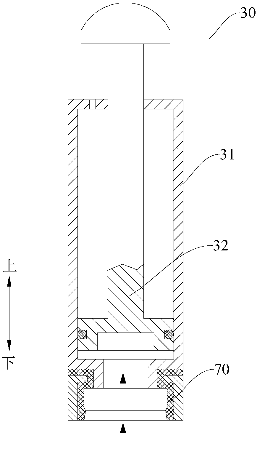
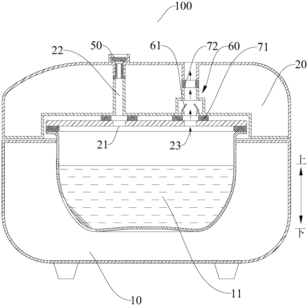
[0071] Such as figure 1 as well as Figure 3-Figure 7 As shown, the cooking appliance 100 includes a pot body 10 , a cover body 20 , an air extraction device 30 , a non-return device 50 and a pressure relief device 60 . The pot body 10 has a cooking cavity 11 with an open top, and a cover body 20 is movably installed on the pot body 10 . The non-return device 50 is fixedly installed on the upper end of the suction channel 22 . The non-return device 50 includes an annular body portion 51 and a sealing piece 52 , the outer peripheral edge of the sealing piece 52 is suspended at the outlet end of the air suction channel 22 . The pressure relief device 60 includes a first sealing ring 71, a pressure relief valve 61 and a second sealing ring 72. The first sealing ring 71 seals the pressure relief device 60 with the pressure relief port 23 to ensure the tightness of the pressure relief port 23. , the second sealing ring 72 seals the pressure relief device 60 with the cover 20 . ...

Embodiment 2

[0078] Such as Figure 2-Figure 6 as well as Figure 8As shown, the cooking appliance 100 includes a pot body 10 , a cover body 20 , an air extraction device 30 , a non-return device 50 and a pressure relief device 60 . The pot body 10 has a cooking cavity 11 with an open top, and a cover body 20 is movably installed on the pot body 10 . The non-return device 50 is fixedly installed at the outlet end of the suction channel 22 . The pressure relief device 60 includes a first sealing ring 71, a pressure relief valve 61 and a second sealing ring 72. The first sealing ring 71 seals the pressure relief device 60 with the pressure relief port 23 to ensure the tightness of the pressure relief port 23. , the second sealing ring 72 seals the pressure relief device 60 with the cover 20 .

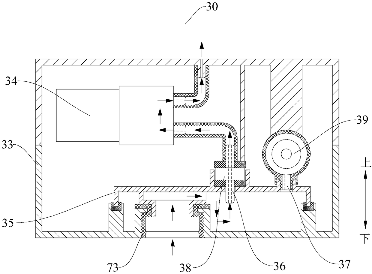
[0079] The air extraction device 30 includes: a housing 33 , a vacuum pump 34 , an air extraction pipe, a first one-way valve 38 , a support plate 35 and a pressure detection module 39 . The housi...

Embodiment 3

[0083] Such as figure 1 , figure 2 and Figure 9 As shown, the cooking appliance 100 includes a pot body 10 , a cover body 20 , an air extraction device 30 , a second one-way valve 40 and a pressure relief device 60 . The pot body 10 has a cooking cavity 11 with an open top, and a cover body 20 is movably installed on the pot body 10 . The second one-way valve 40 is arranged in the middle of the air extraction channel 22 , and the two ends of the second one-way valve 40 are respectively connected to the inner wall of the air extraction channel 22 through the sealing gasket 74 . The pressure relief device 60 includes a first sealing ring 71, a pressure relief valve 61 and a second sealing ring 72. The first sealing ring 71 seals the pressure relief device 60 with the pressure relief port 23 to ensure the tightness of the pressure relief port 23. , the second sealing ring 72 seals the pressure relief device 60 with the cover 20 .

[0084] When the cooking cavity 11 needs to...


PUM


Abstract

The invention discloses a cooking appliance which comprises a pot body, wherein the pot body is provided with a cooking cavity with an open top; a cover body, wherein the cover body is movably arranged on the pot body between an open position and a closed position and the cover body is provided with an air extraction port and an air extraction channel, the inlet end of the air extraction channel is communicated with the air extraction port, and the outlet end of the air extraction channel is communicated with the outside; an air extraction device, wherein the air extraction device is detachably connected to the outlet end of the air extraction channel so as to form negative pressure in a cooking cavity. According to the cooking appliance provided by the embodiment of the invention, by arranging the detachable air extraction device, a user can select different working modes according to requirements, and when negative pressure cooking is required, negative pressure is formed in the cooking cavity through the air extraction device, so that the universality of the air extraction device is improved, meanwhile, the structure of the cover body is simplified, and the cover body is convenient to assemble and install with the air extraction device, so that the cover body is convenient to popularize.

Description

technical field [0001] The invention relates to the technical field of household electrical appliances, in particular to a cooking utensil. Background technique [0002] At present, the air extraction device of the vacuum rice cooker is mainly integrated in the upper cover of the rice cooker. The structure of the air extraction device of different rice cookers is quite different, and there is no standardized structure, resulting in high manufacturing costs; and it cannot be used for other appliances, which is poor in versatility and inconvenient. The promotion and popularization of air extraction devices, so there is room for improvement. Contents of the invention [0003] The present invention aims to solve at least one of the technical problems existing in the prior art. For this reason, the present invention proposes a cooking utensil, the structure of the cooking utensil has high versatility and is easy to popularize. [0004] A cooking appliance according to an embo...

Claims


Application Information

Patent Timeline
IPC IPC(8): A47J27/08
CPCA47J27/08
Inventor 吴慧民邢凤雷马利梁志佳羊小亮邢胜华罗飞龙刘化勇黄韦铭
Owner FOSHAN SHUNDE MIDEA ELECTRICAL HEATING APPLIANCES MFG CO LTD
Why Eureka
Try Eureka