Cleaning robot

A technology for cleaning robots and card slots, which is applied in the field of cleaning robots and can solve problems such as easy friction with the ground and time-consuming water tanks

Inactive Publication Date: 2019-03-12
深圳飞科机器人有限公司
View PDF0 Cites 3 Cited by
  • Summary
  • Abstract
  • Description
  • Claims
  • Application Information

AI Technical Summary

Problems solved by technology

[0004] The purpose of this application is to provide a cleaning robot to solve the problems of time-consuming e...

Method used


Image

  • Cleaning robot
  • Cleaning robot
  • Cleaning robot

Examples


Embodiment Construction

[0033] The following will clearly and completely describe the technical solutions in the embodiments of the present application with reference to the accompanying drawings in the embodiments of the present application.

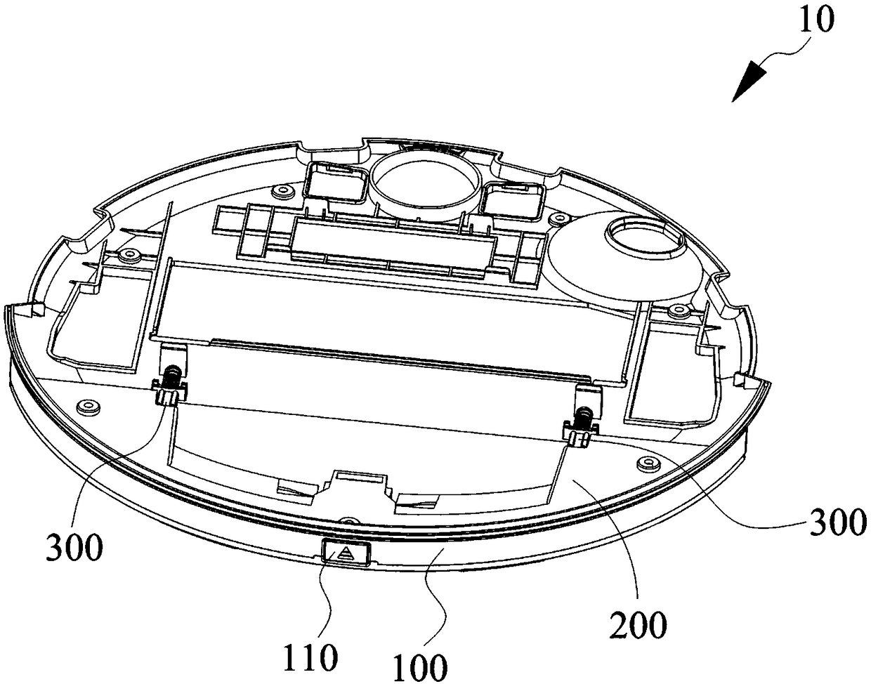
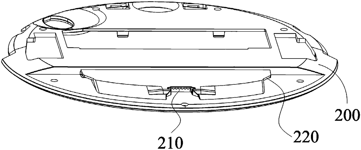
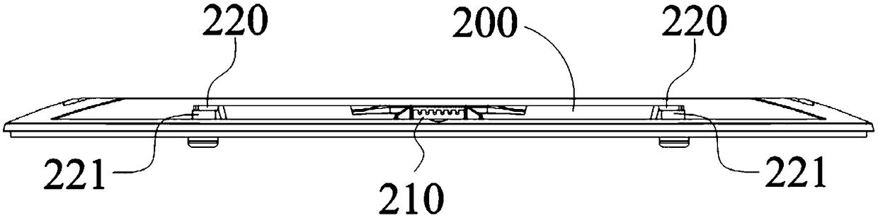
[0034] Such as Figure 1 to Figure 7c As shown, the embodiment of the present application provides a cleaning robot 10 , which has solved the inconvenient and time-consuming problems existing in the installation and removal of the water tank of the existing cleaning robot 10 . The cleaning robot 10 is in the shape of a cylinder as a whole, and has a peripheral surface and a bottom surface; however, according to actual needs, the cleaning robot 10 can also be in the shape of a cuboid or a circular truncated shape. The cleaning robot 10 includes a main body, a carrier 100 disposed on one side of the main body, and an ejection structure 300 . Such as Figure 1-7c , the main body only illustrates a part of the main body, that is, only a bottom shell 200 is shown...


PUM


Abstract

The invention discloses a cleaning robot, which comprises a main body, a bearing piece and an ejection structure. The main body is provided with a card slot, and the bearing piece is provided with a switch assembly matched with the card slot. The detachable connection between the bearing piece and the main body is realized through the buckling or separation between the switch assembly and the cardslot. The ejection structure is elastically connected between the main body and the bearing piece. The ejection structure compresses and elastically supports the main body and the bearing piece whenthe switch assembly and the card slot are buckled. When the switch assembly and the card slot are separated, the ejection structure is ejected to eject the bearing piece from one side of the main body.

Description

technical field [0001] The present application relates to the technical field of robots, in particular to a cleaning robot. Background technique [0002] The cleaning robot integrates the functions of sweeping and mopping the floor, and is favored by many consumers. In order to realize functions such as mopping the floor, a water tank for storing water needs to be provided on the cleaning robot. [0003] The existing water tank installed on the bottom shell of the cleaning robot is locked on the bottom of the cleaning robot through buckles on both sides of the front end of the water tank, although this can realize the fixing of the cleaning robot. However, when the water tank is installed, it takes a certain amount of time to find the position of the locking buckle with the water tank; In the process of taking it out, the water tank is also easy to rub against the ground, causing the water tank to be worn and damaged, or the buckle is easy to scratch the fingers during the...

Claims


Application Information

Patent Timeline
IPC IPC(8): A47L11/24A47L11/28A47L11/40
CPCA47L11/24A47L11/28A47L11/40A47L11/4083A47L2201/00
Inventor 谭跃袁波
Owner 深圳飞科机器人有限公司
Why Eureka
Try Eureka