Dust collection device on laser cutting machine

A technology of laser cutting machine and dust collector, applied in laser welding equipment, welding equipment, metal processing equipment and other directions, can solve the problems of respiratory tract infection, endanger human health, high energy consumption, etc., and achieve the effect of reducing energy consumption

Inactive Publication Date: 2019-03-12
张文辉
View PDF0 Cites 1 Cited by
  • Summary
  • Abstract
  • Description
  • Claims
  • Application Information

AI Technical Summary

Problems solved by technology

The laser cutting machine will produce powder when cutting, and the operator will cause respiratory infection after inhaling a large amount of dust after working for a long time, which will endanger people's health; so some laser cutting machines are equipped with dust suction structures, and some laser cutting machines have laser The device is arranged on the guide rail that can move longitudinally, and the guide rail is fixed on the beam body that can be fed horizontally. The lower side of the beam body is fixed with a dust suction cover, and the dust suction cover is connected with the suction pipe to realize the dust suction on the lower side of the beam body. The whole shell is vacuumed, that is, the part that is not laser cut is also vacuumed during vacuuming; the energy consumption required for vacuuming is relatively large

Method used


Image

  • Dust collection device on laser cutting machine
  • Dust collection device on laser cutting machine
  • Dust collection device on laser cutting machine

Examples


Embodiment

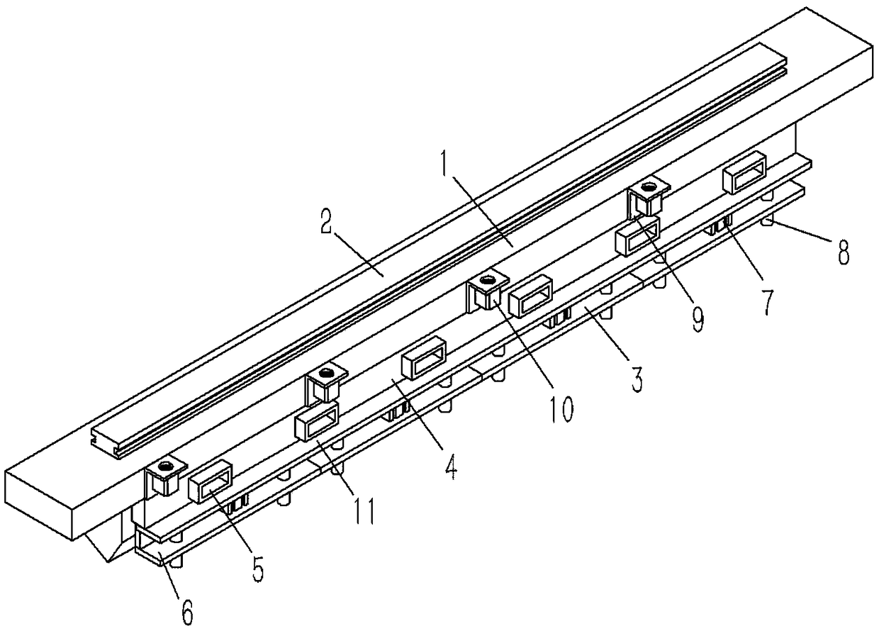
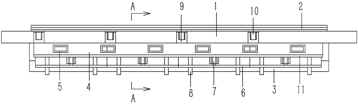
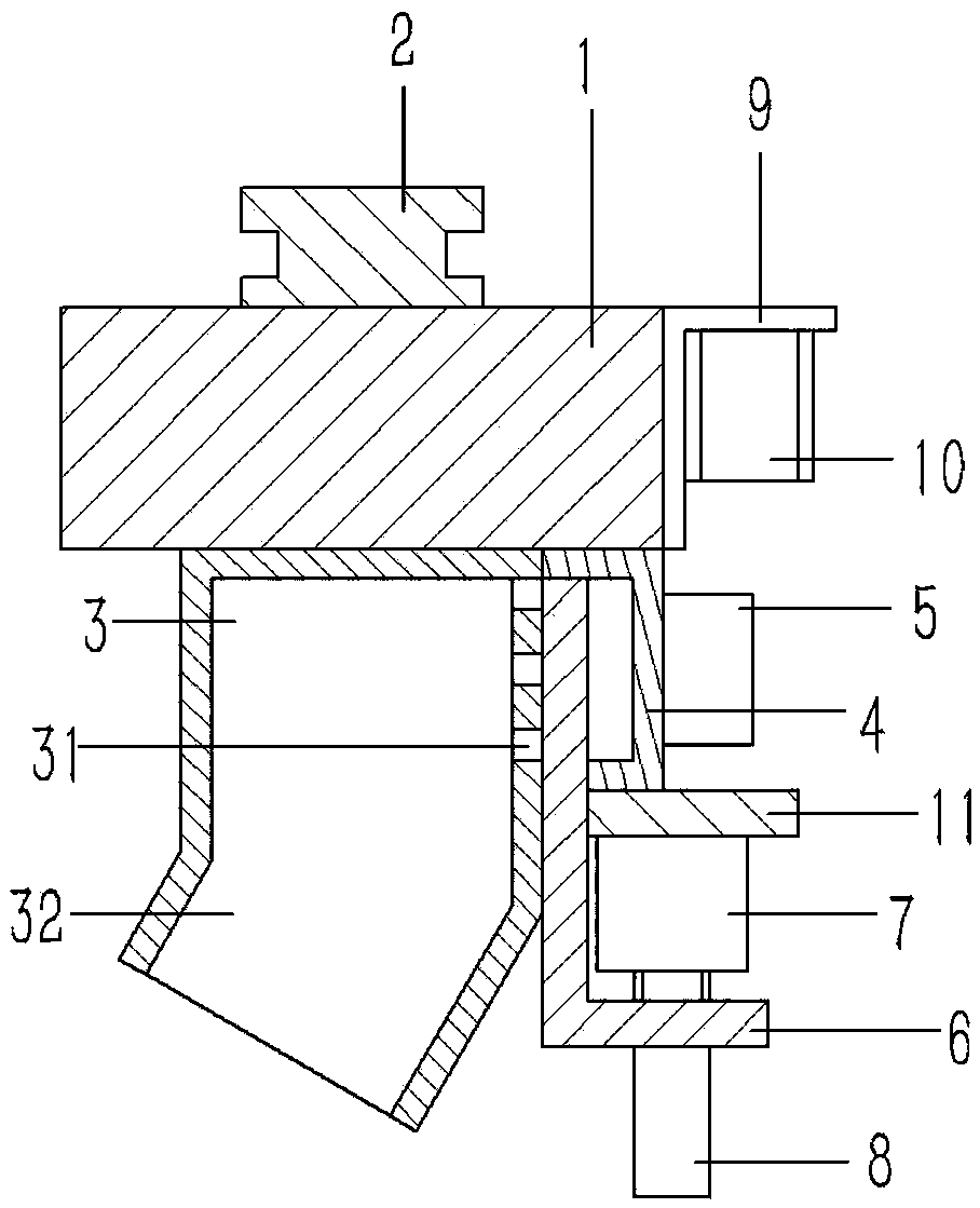
[0016] Example: see Figures 1 to 3 As shown, a dust suction device on a laser cutting machine includes a horizontal feed main beam 1, a horizontal guide rail 2 is fixed on the upper end surface of the feed main beam 1, and a suction suction device fixed on the lower end surface of the feed main beam 1 Dust cover 3, a side wall of the dust collection cover 3 is formed with a number of horizontal dust suction grooves 31, and the outer wall of the dust collection cover 3 is fixed with a dust discharge shell 4 communicating with the dust suction groove 31, and the dust discharge The outer wall of the housing 4 is fixed with a dust discharge pipe 5 communicating with the dust discharge housing 4, and the lower end surface of the dust discharge housing 4 is formed with slots, and several slots are inserted into the slots of the dust discharge housing 4. L-shaped valve plate 6, the valve plate 6 is against the outer wall of the dust collection cover 3 and covers the dust suction gro...


PUM


Abstract

The invention discloses a dust collection device on a laser cutting machine. The dust collection device comprises a transverse feeding main beam, and a transverse guide rail is fixed to the upper endface of the feeding main beam; a dust collection cover is fixed to the lower end face of the feeding main beam; a plurality of transverse dust collection grooves are formed in the side wall of one side of the dust collection cover; a dust discharge shell which communicates with the dust collection grooves is fixed to the outer side wall of the dust collection cover; a dust discharge pipe which communicates with the dust discharge shell is fixed to the outer side wall of the dust discharge shell; insertion grooves are formed in the lower end face of the dust discharge shell; a plurality of L-shaped valve plates are inserted in the insertion grooves of the dust discharge shell; the valve plates abut against the outer side wall of the dust collection cover and cover the dust collection grooves of the dust collection cover; the adjacent valve plates abut against each other; the valve plates are composed of vertical parts inserted on the dust discharge shell and horizontal parts on the lower side of the dust discharge shell; a supporting plate is fixed to the lower end face of the dust discharge shell; cylinders are fixed to the supporting plate; and piston rods of the cylinders are fixed to the horizontal parts of the valve plates. According to the dust collection device, dust collection can be achieved during laser cutting of specific parts, and energy consumption is effectively reduced.

Description

Technical field: [0001] The invention relates to the technical field of laser processing, in particular to a dust suction device on a laser cutting machine. Background technique: [0002] The laser cutting machine focuses the laser light emitted from the laser device into a high power density laser beam through the optical path system. The laser beam irradiates the surface of the workpiece to make the workpiece reach the melting point or boiling point, and at the same time, the high-pressure gas coaxial with the beam blows away the molten or vaporized metal. The laser cutting machine will produce powder when cutting, and the operator will cause respiratory infection after inhaling a large amount of dust after working for a long time, which will endanger people's health; so some laser cutting machines are equipped with dust suction structures, and some laser cutting machines have laser The device is arranged on the guide rail that can move longitudinally, and the guide rail ...

Claims


Application Information

Patent Timeline
Patent Type & Authority Applications(China)
IPC IPC(8): B23K26/70B23K26/38
CPCB23K26/70B23K26/38B23K26/702
Inventor 张文辉
Owner 张文辉
Why Eureka
Try Eureka