Laser cutting machine

A technology of laser cutting machine and cutting mechanism, applied in laser welding equipment, welding equipment, metal processing equipment and other directions, can solve problems such as safety accidents, easy fatigue of cutting materials, and occurrence, and achieve the effect of improving work efficiency

Inactive Publication Date: 2021-06-29
杨慧
View PDF0 Cites 1 Cited by
  • Summary
  • Abstract
  • Description
  • Claims
  • Application Information

AI Technical Summary

Problems solved by technology

[0004] In order to overcome the shortcoming of safety accidents due to the fatigue caused by manual lifting and cutting of raw materials for a long time, the technical problem to be solved is to provide a laser cutting machine that can automatically load materials

Method used


Image

  • Laser cutting machine
  • Laser cutting machine
  • Laser cutting machine

Examples


Embodiment 1

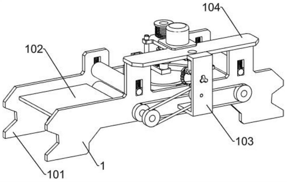
[0030] A laser cutting machine such as figure 1 As shown, it includes a support frame, a power mechanism and a cutting mechanism, including the first support plate 1 of the support frame, the second support plate 101, the connecting plate 102, the vertical support 103, the upper support 104 and the side support 105, the first support plate 1 and the second support plate 101 are symmetrically arranged front and rear, the front and rear sides of the connecting plate 102 are respectively fixedly connected to the inside of the first support plate 1 and the second support plate 101, and the lower end of the vertical support 103 is fixedly connected to the front of the first support plate 1 side, the lower sides of both ends of the upper bracket 104 are respectively fixedly connected to the first support plate 1, the front side of the upper bracket 104 is fixedly connected to the upper end of the vertical bracket 103, and the right end of the side bracket 105 is fixedly connected to ...

Embodiment 2

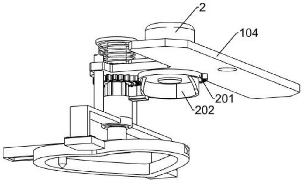
[0033] On the basis of Example 1, such as figure 2 , Figure 4 and Figure 5 As shown, the power mechanism includes a motor 2, a missing gear 201, a circular cam 202, a spline sleeve 203 and a first spur gear 204, the motor 2 is fixedly connected to the upper side of the upper bracket 104, and the missing gear 201 is fixedly connected to the top of the motor 2 The power output shaft, the circular cam 202 is fixedly connected to the underside of the missing gear 201, the upper end of the spline sleeve 203 is rotatably connected to the left end of the upper bracket 104, the first straight gear 204 is fixedly connected to the lower end of the spline sleeve 203, the first straight The gear 204 meshes with the missing gear 201 .

[0034]Start the power mechanism after turning on the power supply during use, the motor 2 rotates and drives the missing gear 201 to rotate, and the missing gear 201 rotates to drive the circular cam 202 to rotate. The rotation of the straight gear 20...

Embodiment 3

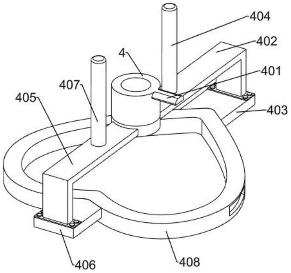
[0038] On the basis of Example 2, such as Figure 2-Figure 5 As shown, the track control mechanism includes a connecting sleeve 4, a touch plate 401, a first connecting frame 402, a first fixing plate 403, a first slide bar 404, a second connecting frame 405, a second fixing plate 406, a second sliding Rod 407 and cutting guide rail 408, the connecting sleeve 4 is rotatably connected to the lower part of the rotating shaft 3, the touch plate 401 is fixedly connected to the upper end of the connecting sleeve 4, the left end of the first connecting frame 402 is fixedly connected to the lower end of the connecting sleeve 4, the first fixed The right end of the plate 403 is connected to the lower right end of the first connecting frame 402 by bolts, the lower end of the first sliding rod 404 is fixedly connected to the upper side of the first connecting frame 402 near the end of the connecting sleeve 4, and the first sliding rod 404 slides with the upper bracket 104 connection, th...


PUM


Abstract

The invention relates to a cutting machine, in particular to a laser cutting machine. According to the laser cutting machine, automatic feeding is achieved. The laser cutting machine comprises a supporting frame, a supporting frame first supporting plate, a supporting frame second supporting plate, a supporting frame connecting plate, a supporting frame vertical support, a supporting frame upper support and a supporting frame side support, the first supporting plate and the second supporting plate are symmetrically arranged front and back, the front side and the rear side of the connecting plate are fixedly connected to the inner side of the first supporting plate and the inner side of the second supporting plate respectively, and one end of the vertical support is fixedly connected to one side of the first supporting plate; and one sides of the two ends of the upper support are fixedly connected to the first supporting plates respectively, one side of the upper support is fixedly connected to the other end of the vertical support, one end of the side support is fixedly connected to one side of the vertical support, a power mechanism is arranged on the upper support, a the cutting mechanism is arranged on the lower portion of the upper support. According to the laser cutting device, laser cutting of raw materials is achieved through the power mechanism and the cutting mechanism, manual holding of the laser cutting device for cutting is omitted, and the working efficiency is improved.

Description

technical field [0001] The invention relates to a cutting machine, in particular to a laser cutting machine. Background technique [0002] Laser cutting process replaces the traditional mechanical knife with an invisible beam. It has the characteristics of high precision, fast cutting, not limited to cutting patterns, automatic typesetting saves materials, smooth incision, and low processing cost. It will gradually improve or replace it. Traditional metal cutting process equipment, the mechanical part of the laser cutter head has no contact with the work, and will not scratch the work surface during work. The laser cutting speed is fast, the incision is smooth and flat, generally no subsequent processing is required, the cutting heat-affected zone is small, and the plate The deformation is small, the slit is narrow, the slit has no mechanical stress, no shear burr, high processing precision, good repeatability, and does not damage the surface of the material. [0003] Most ...

Claims


Application Information

Patent Timeline
Patent Type & Authority Applications(China)
IPC IPC(8): B23K26/38B23K26/08
CPCB23K26/0823B23K26/38
Inventor 杨慧
Owner 杨慧
Why Eureka
Try Eureka