Continuous cap screwing equipment

A technology of equipment and cap sleeves, applied in screw caps and other directions, can solve problems such as low work efficiency and complex structure

Inactive Publication Date: 2019-03-12
广东嘉能可食品有限公司
View PDF0 Cites 0 Cited by
  • Summary
  • Abstract
  • Description
  • Claims
  • Application Information

AI Technical Summary

Problems solved by technology

In this beverage bottle capping device, the capping sleeve is in a fixed position, and the capping work is performed only through expansion and contraction, which requires a conveyor belt to send the beverage bottle to the capping station. After the completion, it will continue to move forward, convey the beverage bottle that has been capped forward, and convey the next beverage bottle to be capped to the capping station, that is to say, it is a conveyor belt that requires gap feeding, and its structure is relatively complicated. and low efficiency

Method used


Image

  • Continuous cap screwing equipment
  • Continuous cap screwing equipment
  • Continuous cap screwing equipment

Examples


Embodiment Construction

[0011] Below with reference to the accompanying drawings, through the description of the implementation examples, the specific embodiments of the present invention, such as the shape, structure, mutual position and connection relationship between each part, the role and working principle of each part, etc., will be further described. detailed instructions.

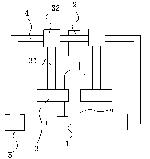
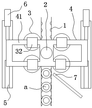
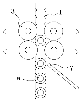
[0012] Such as figure 1 , 2 3. The continuous capping equipment of the present invention includes a conveyor belt 1 for conveying beverage bottles a, a capping station is provided in the conveying direction of the conveyor belt 1, a capping device is provided above the capping station, and the capping device includes Capping sleeve 2, clamping wheel 3 for clamping the bottle body of beverage bottle a and gantry 4 for fixing capping sleeve 2 and clamping wheel 3, both sides of the screwing station are provided with The length direction of the conveyor belt 1 is parallel to the track 5, the bottom of both ends of the gantr...


PUM


Abstract

The invention provides continuous cap screwing equipment which is simple in structure and high in work efficiency. The cap screwing equipment comprises a conveying belt, wherein the conveying belt isused for conveying drink bottles. The conveying belt is provided with a cap screwing station in the conveying direction. A cap screwing device is arranged above the cap screwing station and comprisesa cap screwing sleeve, clamping wheels and a portal frame, wherein the clamping wheels are used for clamping a bottle body of each drink bottle, and the portal frame is used for fixing the cap screwing sleeve and the clamping wheels. Tracks are arranged at the two sides of the cap screwing station, wherein the tracks are parallel with the length direction of the conveying belt. The bottoms of thetwo ends of the portal frame are connected with the tracks in a sliding manner. A linear air cylinder is arranged at the stroke of each track, wherein the linear air cylinders are in driving connection with the bottom of the portal frame. Wheel shafts of the clamping wheels are connected with a clamping wheel machine seat. The portal frame is provided with a sliding rod which is connected with theclamping wheel machine seat through bearings.

Description

technical field [0001] The invention relates to the technical field of beverage bottle filling processing equipment, in particular to a continuous capping equipment. Background technique [0002] At present, most beverage bottle screwing devices in automatic beverage packaging equipment transmit beverage bottles through conveyor belts with pawls on both ends of the side walls, and send the beverage bottles to the bottom of the screwing station, and place them on the beverage bottle by screwing the capping sleeve. The cap at the mouth of the bottle. When screwing the cap, the fixation of the beverage bottle is completed by the ratchets on the side walls at both ends of the bottom conveyor belt. In this beverage bottle capping device, the capping sleeve is in a fixed position, and the capping work is performed only through expansion and contraction, which requires a conveyor belt to send the beverage bottle to the capping station. After the completion, it will continue to mo...

Claims


Application Information

Patent Timeline
Patent Type & Authority Applications(China)
IPC IPC(8): B67B3/20
CPCB67B3/20
Inventor 劳玮锋陈汉东翁永进
Owner 广东嘉能可食品有限公司
Why Eureka
Try Eureka