Material disinfecting equipment

A technology of disinfection equipment and assembly, which is applied in the field of materials, can solve the problems of single function of material disinfection equipment, achieve the effects of convenient spraying of disinfectant, convenient power output, and prevention of dry running

Inactive Publication Date: 2020-09-18
杨雨夕
View PDF0 Cites 0 Cited by
  • Summary
  • Abstract
  • Description
  • Claims
  • Application Information

AI Technical Summary

Problems solved by technology

[0002] Material disinfection equipment is a commonly used equipment in the material field, but half of the material disinfection equipment has a single function

Method used


Image

  • Material disinfecting equipment
  • Material disinfecting equipment
  • Material disinfecting equipment

Examples


specific Embodiment approach 1

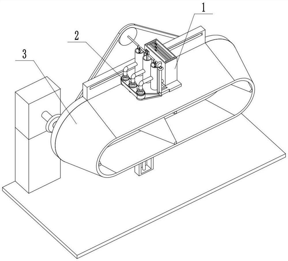
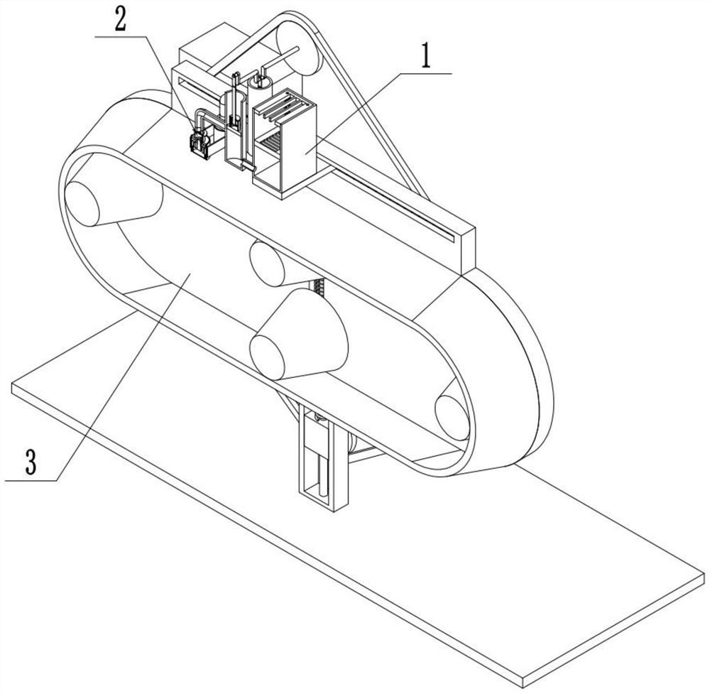
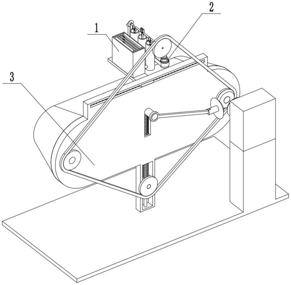
[0029] Combine below Figure 1-13 Describe this embodiment, a material disinfection equipment, including a liquid spray assembly 1, a spray head assembly 2, and a carrying assembly 3, characterized in that: the liquid spray assembly 1 is connected to the spray head assembly 2, and the spray head assembly 2 is connected to the carrier assembly 3.

specific Embodiment approach 2

[0031] Combine below Figure 1-13Describe this embodiment, this embodiment will further explain Embodiment 1, the liquid spray assembly 1 includes a conduit 1-1, a piston sleeve 1-2, a crankshaft 1-3, a liquid storage outer frame 1-4, and a filter plate One 1-5, rectangular filter hole one 1-6, inner end sliding column one 1-7, inner end sliding column push spring one 1-8, crankshaft connecting rod 1-9, piston connecting rod 1-10, limit plate 1-11, piston plate 1-12, arc slot 1-13, arc bar 1-14, arc bar push spring 1-15, filter plate two 1-16, rectangular filter hole two 1-17 , Connecting pipe 1-18, the conduit 1-1 is fixedly connected and communicated with the piston casing 1-2, the connecting pipe 1-18 is fixedly connected to the piston casing 1-2 and the liquid storage outer frame 1-4, and the through pipe 1- 18 communicates with the piston sleeve 1-2 and the liquid storage outer frame 1-4, the inner end sliding column one 1-7 is fixedly connected with the liquid storage o...

specific Embodiment approach 3

[0033] Combine below Figure 1-13 Describe this embodiment. This embodiment will further explain Embodiment 1. The nozzle assembly 2 includes a rotatable sleeve 2-1, an axial limit plate 2-2, a connecting sleeve 2-3, and an adjustment plate 2. -4, connecting sleeve two 2-5, closing rod 2-6, wedge-shaped sleeve 2-7, through hole one 2-8, through hole two 2-9, inner end sliding column 2-10, inner end sleeve 2-11, the through hole 2-12 of the inner end casing, the spray hole 2-13, the axial limit plate 2-2 is connected with the rotatable sleeve 2-1 in rotation, and the connecting sleeve 2-3 is connected with the axial limit plate. The bit plate 2-2 is fixedly connected, the adjusting disc 2-4 is rotationally connected with the connecting sleeve 1 2-3, the adjusting disc 2-4 is rotationally connected with the connecting sleeve 2 2-5, and the adjusting disc 2-4 is connected with the closing rod 2- 6 Sliding fit connection, the closing rod 2-6 is rotationally connected with the sec...


PUM


Abstract

The invention relates to the field of materials, in particular to material disinfecting equipment. The material disinfecting equipment can realize delivery of materials needing to be disinfected, besides, dry running of the equipment can be avoided, the amount of disinfecting liquid sprayed out can be adjusted, further the disinfection effect can be convenient to change, and when delivery equipment becomes invalid, a manual movement manner can be used for changing the position where the disinfecting liquid is sprayed out. The material disinfecting equipment comprises a liquid spraying assembly, a spray head assembly and a delivery assembly, wherein a bevel IV is used for driving a bevel III to rotate, the bevel III drives a transmission bevel shaft A to rotate, a transmission bevel shaft Adrives a transmission belt II to move, and a rotatable casing pipe is driven by the transmission belt II to rotate; and besides, a transmission belt I drives other rotatable casing pipes to rotate, so that power output is convenient. Besides, when the delivery capacity of the delivery belt becomes invalid, a fixing plate slides along a power bottom plate, so that the fixing plate drives the liquid spraying assembly, the spray head assembly and the delivery assembly to move at the same time, and the disinfecting liquid is convenient to spray.

Description

technical field [0001] The invention relates to the field of materials, in particular to a material disinfection equipment. Background technique [0002] Material disinfection equipment is a commonly used equipment in the material field, but half of the material disinfection equipment has a single function. Contents of the invention [0003] The purpose of the present invention is to provide a kind of material disinfection equipment, which can realize the carrying of materials that need to be sterilized; at the same time, it can prevent the device from running dry; Change the position where the disinfectant is sprayed by manually moving. [0004] The purpose of the present invention is achieved through the following technical solutions: [0005] A material disinfection equipment, including a liquid spray assembly, a spray head assembly, and a carrying assembly, characterized in that: the liquid spray assembly is connected to the spray head assembly, and the spray head as...

Claims


Application Information

Patent Timeline
Patent Type & Authority Applications(China)
IPC IPC(8): A61L2/18A61L2/26B01D29/03B01D29/58
CPCA61L2/18A61L2/26B01D29/03B01D29/58
Inventor 杨雨夕
Owner 杨雨夕
Why Eureka
Try Eureka