[0016] The following is a further detailed description through specific implementations:
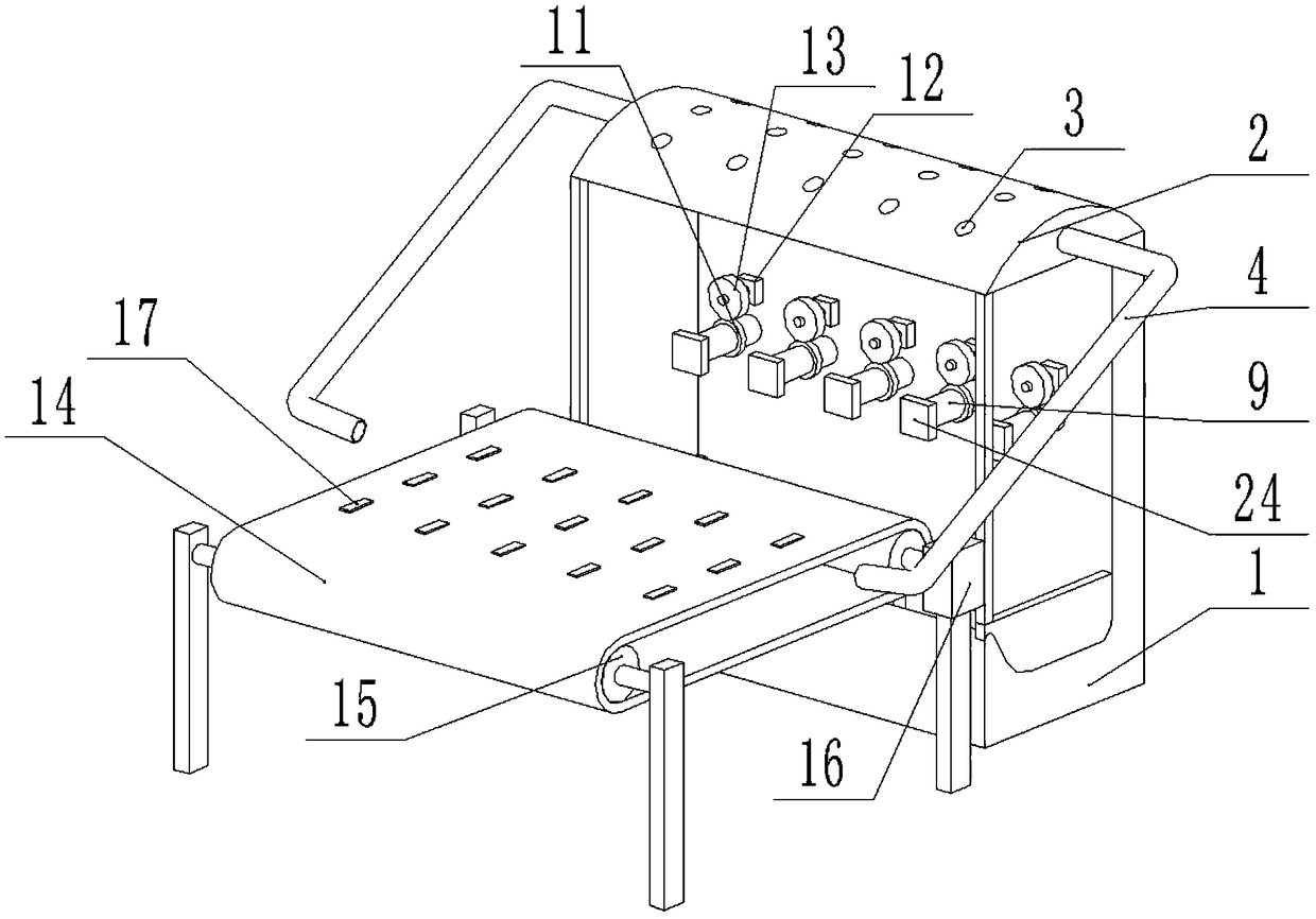
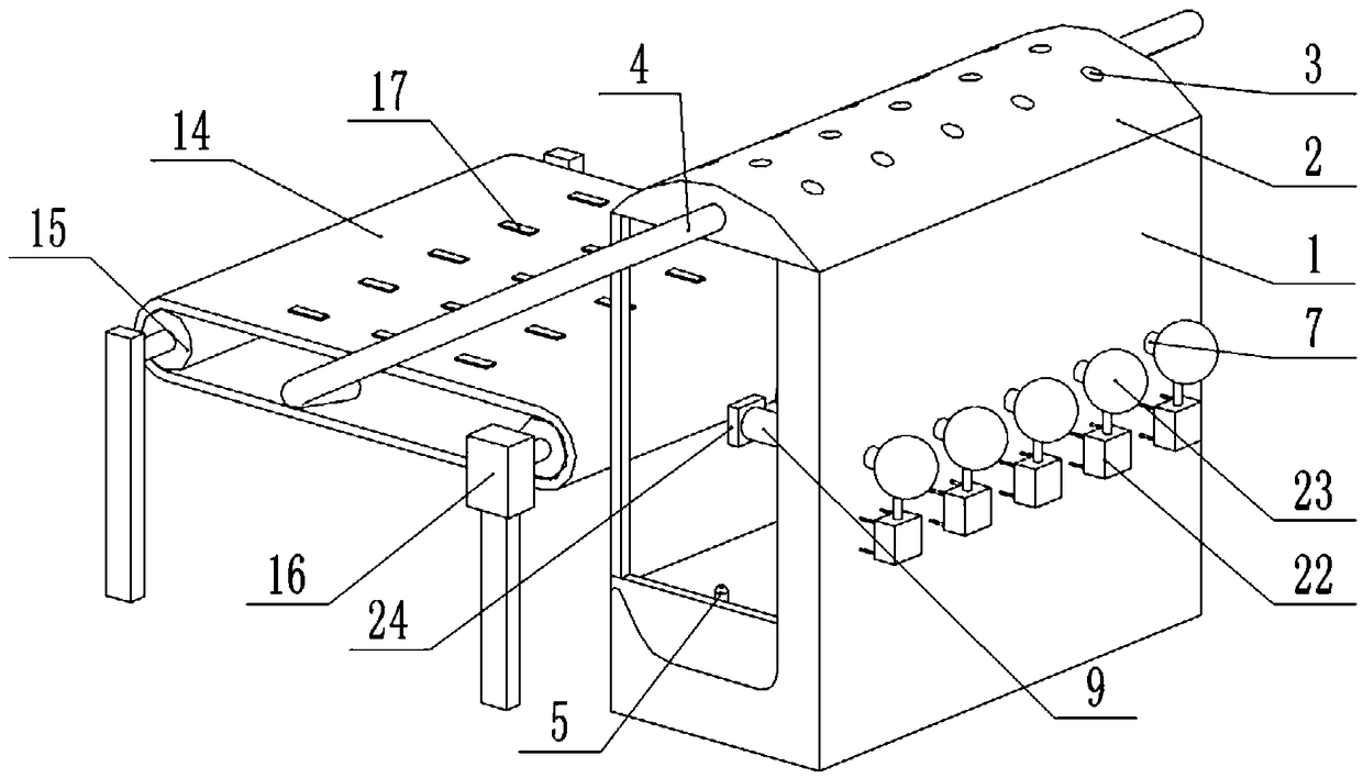
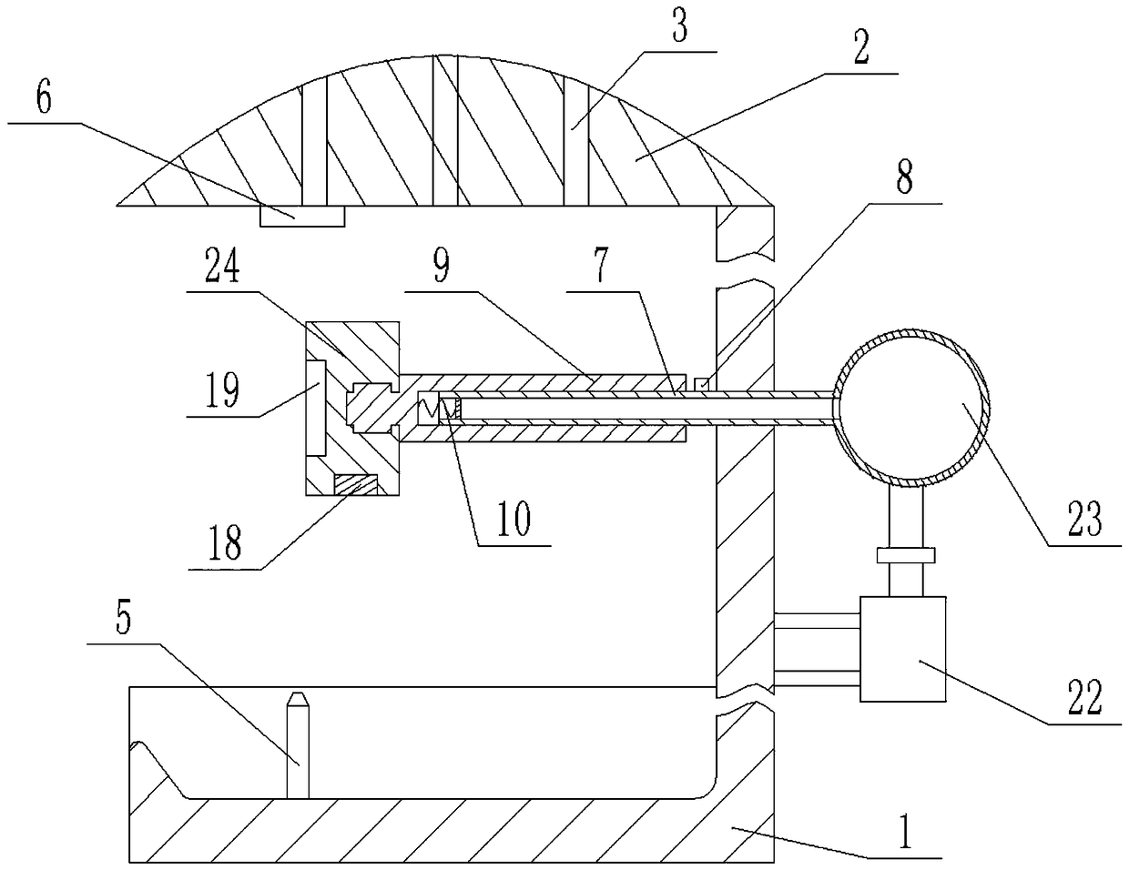
[0017] The reference signs in the drawings of the specification include: base 1, top cover 2, air passage 3, air outlet pipe 4, flame spray gun 5, first resistance 6, telescopic rod 7, second solenoid valve 8, clamping rod 9, First spring 10, second friction wheel 11, motor 12, first friction wheel 13, conveyor belt 14, roller 15, driver 16, first magnetic block 17, second magnetic block 18, groove 19, second spring 20 , Splint 21, air pump 22, air bag 23, jaw 24.
[0018] The embodiment is basically as attached figure 1 , figure 2 Shown:
[0019] The foam blowing machine includes a base 1, a top cover 2 is provided on the top of the base 1, the middle of the top cover 2 is arched upward, and the top cover 2 is provided with a hollow accommodating cavity in which sodium bicarbonate particles are contained. The top cover 2 is provided with a plurality of air passages 3 in the vertical direction. The two ends of the air passages 3 penetrate the upper and lower end surfaces of the top cover 2 and the air passages 3 are not connected with the containing cavity.
[0020] The base 1 is provided with a telescopic unit. Combine image 3 The telescopic unit includes a telescopic rod 7, an airbag 23, and an inflator. The inflator is an inflator 22, which is fixedly arranged on the base 1. One end of the airbag 23 is connected with a one-way valve, which is connected to the inflator 22 The output end is connected, the one-way valve is only for gas to flow from the inflator 22 to the airbag 23, and the other end of the airbag 23 is connected with a first solenoid valve; the telescopic rod 7 is hollow and open at both ends, and the telescopic rod 7 is horizontally fixed on the base 1 , One end of which is communicated with the first solenoid valve; the upper part of the telescopic rod 7 close to the first solenoid valve is connected with a second solenoid valve 8. The first solenoid valve and the second solenoid valve 8 are both normally open solenoid valves. The expansion unit also includes a first resistor 6, a second resistor, and a third resistor, all of which are fixedly arranged on the lower end surface of the top cover 2 and arranged side by side. The first resistor 6 is electrically connected to the first solenoid valve and is in the same closed circuit, the second resistor is electrically connected to the second solenoid valve 8 and is in the same closed circuit, and the third resistor is electrically connected to the air pump 22 and is in the same closed circuit. All of them are negative temperature coefficient thermistors. The first resistor 6 and the third resistor have a resistance value of 8000Ω when the temperature is 25℃, when the temperature is 100℃, the resistance value is 150Ω, and when the temperature is 150℃, the resistance value is 8000Ω. When the temperature of the second resistor is 25℃, the resistance value is 5000Ω, when the temperature is 70℃, the resistance value is 150Ω, when the temperature is 150℃, the resistance value is 17Ω; when the temperature of the first resistor 6 reaches 100℃ , The first solenoid valve is energized with current enough to close it, when the temperature of the second resistor reaches 120°C, the second solenoid valve 8 is energized with current enough to close it, and when the temperature of the third resistor reaches 100°C, the air pump 22 It can be started and inflated gradually.
[0021] The base 1 is provided with a clamping unit. The clamping unit includes a clamping rod 9 and a pliers 24. The clamping rod 9 is hollow inside and is sheathed on the telescopic rod 7, and the clamping rod 9 is in sliding and sealing contact with the telescopic rod 7 . The left end of the inner wall of the clamping rod 9 is fixedly provided with a first spring 10, and the right end of the first spring 10 is fixedly connected with the left end of the telescopic rod 7. The end of the clamping rod 9 away from the telescopic rod 7 is horizontally provided with a spline, the end of the pliers 24 close to the spline is provided with a matching spline groove, and the pliers 24 are detachably connected to the clamping rod 9 through the splines; The clamping rod 9 is also concentrically fixed with a second friction wheel 11. A motor 12 is fixed on the base 1, a reducer is arranged on the output end of the motor 12, and a first friction wheel 13 is fixed concentrically on the output end of the reducer. The axial direction of the first friction wheel 13 is the same as that of the second friction wheel. The axial direction of 11 is parallel, and the circumferential wall of the first friction wheel 13 and the circumferential wall of the second friction wheel 11 are tightly abutted.
[0022] A heating unit is provided on the base 1, and the heating unit includes a flame spray gun 5. The flame spray gun 5 is fixedly arranged on the base 1 and vertically upward, and the flame spray gun 5 is located directly below the clamping rod 9.
[0023] The blowing machine also includes a transmission unit. The transmission drive includes a conveyor belt 14 mechanism. The conveyor belt 14 mechanism includes a conveyor belt 14 and two rollers 15. The conveyor belt 14 is tensioned and wound on the rollers 15, and a number of brackets and rollers 15 are fixed on the ground. The rotation is arranged at the upper end of the bracket, and one of the rollers 15 is rotated by a driver 16. The conveying direction of the conveyor belt 14 is parallel to the moving direction of the clamping rod 9, and the conveyor belt 14 can be in contact with the lower end surface of the jaw 24. A number of first magnetic blocks 17 are embedded on the conveyor belt 14, and the lower end surface of the jaw 24 is embedded with There are a number of second magnetic blocks 18, and the opposite sides of the first magnetic block 17 and the second magnetic block 18 have different magnetic poles. The machine base 1 is provided with an air outlet tube 4, one end of the air outlet tube 4 is connected with the containing cavity, and the other end of the air outlet tube 4 is fixedly arranged on the bracket and aligned with the conveyor belt 14.
[0024] Combine Figure 4 The pliers 24 includes a base. The left end of the base is provided with a groove 19 for placing wine glasses. Both sides of the inner wall of the groove 19 are fixed with a second spring 20, and the second spring 20 is fixed with an arc Shaped splint 21.
[0025] The specific implementation process is as follows:
[0026] Start the driver 16 first, the driver 16 drives the roller 15 to rotate, and the roller 15 drives the conveyor belt 14 to move. Then the two clamping plates 21 are pushed apart, and the wine glass to be processed is placed between the two clamping plates 21. After the clamping plates 21 are released, the two clamping plates 21 clamp the wine glass under the action of the second spring 20. Then start the motor 12, the output end of the motor 12 drives the output end of the reducer to rotate, and the output end of the reducer drives the first friction wheel 13 to rotate. The friction force between the first friction wheel 13 and the second friction wheel 11 is large, so The first friction wheel 13 drives the second friction wheel 11 to rotate, the second friction wheel 11 drives the clamping rod 9 to rotate, and the clamping rod 9 drives the wine glass to rotate; then start the flame spray gun 5, and the flame spray gun 5 generates an open flame and heats the wine glass. . When the flame spray gun 5 produces an open flame, the temperature of the open flame is extremely high. It not only heats the wine glass but also heats the air near the open flame. After the air is heated, the density decreases and gradually rises. At this time, the hot air interacts with the first resistor 6, the second resistor and The third resistance contact. When the temperature of the second resistance reaches 70℃ and above, the second solenoid valve 8 is energized and closed. When the temperature of the first resistance 6 and the third resistance reaches 100℃ and above, the first solenoid valve Power is turned on and turned off, and at the same time the inflator 22 is activated, the inflator 22 fills the airbag 23 with gas, and the gas in the airbag 23 cannot pass through the first solenoid valve, so the airbag 23 gradually expands and accumulates more and more gas. After the bubbling is over, turn off the flame spray gun 5 and the motor 12, the open flame disappears, the motor 12 stops rotating, and the clamping rod 9 also stops rotating. At this time, the temperature of the hot air gradually decreases, the first resistor 6, the second resistor and the third resistor The temperature of the airbag 23 also gradually decreases. When the temperature of the first resistor 6 and the third resistor drops below 100°C, the inflator 22 is turned off, the first solenoid valve is de-energized and opened. Under the action, it is quickly pressed into the telescopic rod 7, and the gas pushes the clamping rod 9 outward. The clamping rod 9 drives the pliers 24 and the wine glass close to the conveyor belt 14, when the second magnetic block 18 on the pliers 24 and the conveyor belt 14 When the first magnetic block 17 on the upper part contacts, the pliers 24 are fixed on the conveyor belt 14. Since the pliers 24 are splined with the clamping rod 9, the spline connection cannot fix the pliers 24 in the horizontal direction. The pliers 24 will move with the conveyor belt 14, and finally the pliers 24 will be separated from the clamping rod 9. When the temperature of the second resistor drops below 70°C, the second solenoid valve 8 is de-energized and opened. At this time, the clamping rod 9 moves in the direction of the telescopic rod 7 under the elastic restoring force of the first spring 10, and the clamping The gas in the holding rod 9 is discharged from the second solenoid valve 8. Finally, the new wine glass is clamped on the new pliers 24, and then the pliers 24 are splined to the clamping rod 9 to perform the next round of blowing processing.
[0027] In the above process, after the hot air rises, it will contact the top cover 2 and heat the accommodating cavity of the top cover 2. The sodium bicarbonate particles in the accommodating cavity are heated and decompose carbon dioxide. The carbon dioxide is emitted to the conveyor belt 14 through the air outlet pipe 4 The temperature of the wine glass is lowered, and the temperature of the carbon dioxide is not low after a certain heating, so it can prevent the wine glass from breaking due to excessive temperature difference when cooling the wine glass.