A new finite element modeling method for insect wings with flexible vein nodes
A modeling method and finite element technology, applied in instrumentation, design optimization/simulation, calculation, etc., can solve problems such as inability to accurately simulate mechanical properties such as the overall stiffness of wings
- Summary
- Abstract
- Description
- Claims
- Application Information
AI Technical Summary
Problems solved by technology
Method used
Image
Examples
Embodiment 1
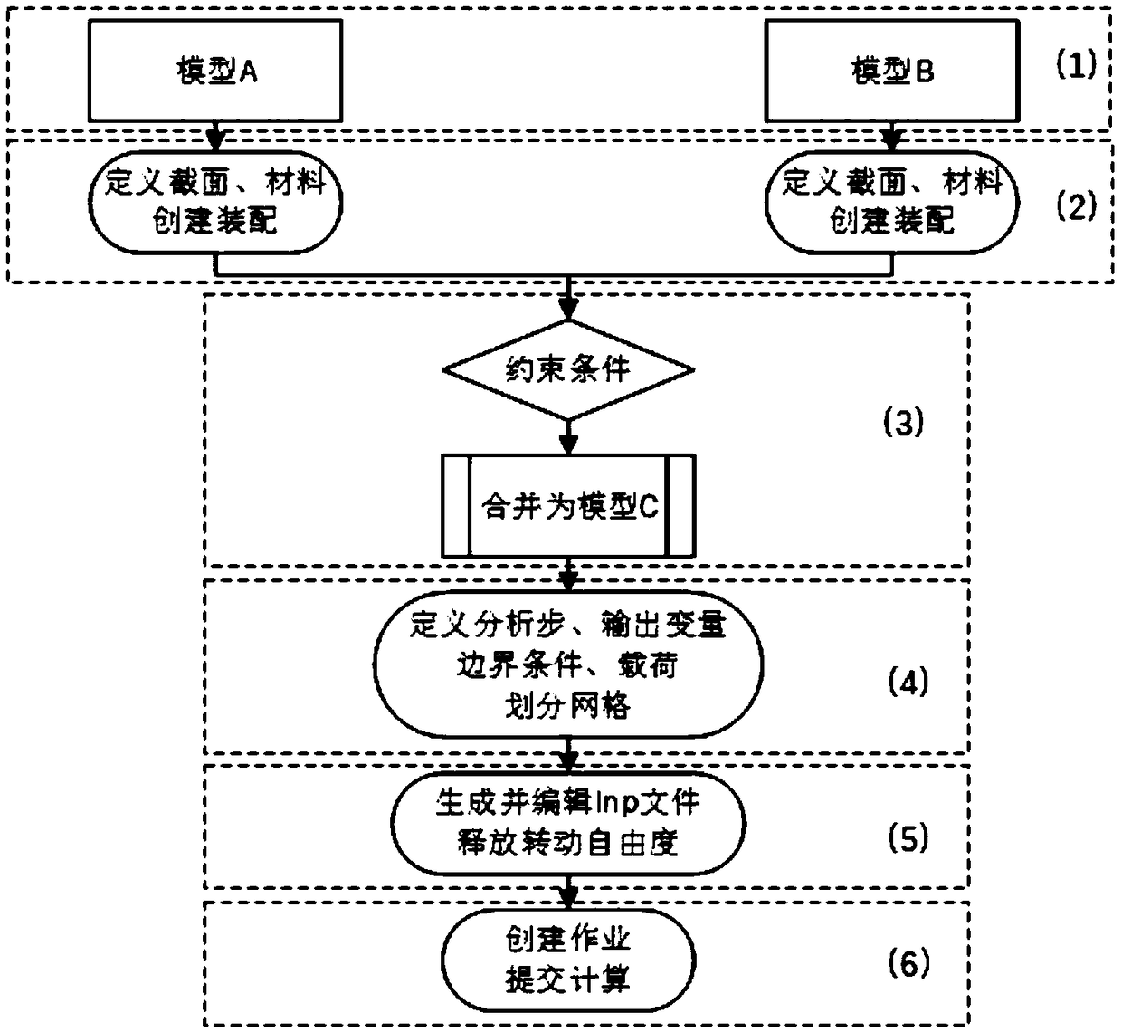
[0046] Such as figure 1 , a new finite element modeling method for insect wings with flexible vein nodes, including the following steps:
[0047](1) Basic modeling, build model A and model B. Model A: wing veins, images of insect wings obtained by scanning, processed by AutoCAD software and imported into Abaqus software to create 3D-deformable-wire type parts; Model B: wing membranes, images of wings obtained by scanning, processed by AutoCAD software After AutoCAD processing, it is imported into Abaqus software to create 3D-deformable-shell type parts.
[0048] (2) Give the component section properties, material parameters, and create an assembly. For model A, assign a circular section, and set the inner diameter and thickness; for model B, assign a uniform thickness shell section, and set the thickness.
[0049] (3) Set constraints, bind model A and model B as model C. Define the binding constraint type to limit the relative displacement and rotation between model A and ...
Embodiment 2
[0061] Such as figure 1 , a new finite element modeling method for insect wings with flexible vein nodes, including the following steps:
[0062] (1) Basic modeling, build model A and model B. Model A: wing veins, images of insect wings obtained by scanning, processed by AutoCAD software and imported into Abaqus software to create 3D-deformable-wire type parts; Model B: wing membranes, images of wings obtained by scanning, processed by AutoCAD software After AutoCAD processing, it is imported into Abaqus software to create 3D-deformable-shell type parts.
[0063] (2) Give the component section properties, material parameters, and create an assembly. For model A, assign a circular section, and set the inner diameter and thickness; for model B, assign a uniform thickness shell section, and set the thickness.
[0064] (3) Set constraints, bind model A and model B as model C. Define the binding constraint type to limit the relative displacement and rotation between model A and...
Embodiment 3
[0076] Such as figure 1 , a new finite element modeling method for insect wings with flexible vein nodes, including the following steps:
[0077] (1) Basic modeling, build model A and model B. Model A: wing veins, images of insect wings obtained by scanning, processed by AutoCAD software and imported into Abaqus software to create 3D-deformable-wire type parts; Model B: wing membranes, images of wings obtained by scanning, processed by AutoCAD software After AutoCAD processing, it is imported into Abaqus software to create 3D-deformable-shell type parts.
[0078] (2) Give the component section properties, material parameters, and create an assembly. For model A, assign a circular section, and set the inner diameter and thickness; for model B, assign a uniform thickness shell section, and set the thickness.
[0079] (3) Set constraints, bind model A and model B as model C. Define the binding constraint type to limit the relative displacement and rotation between model A and...
PUM
 Abstract
Description
Claims
Application Information
 - R&D
- Intellectual Property
- Life Sciences
- Materials
- Tech Scout
- Unparalleled Data Quality
- Higher Quality Content
- 60% Fewer Hallucinations
Browse by: Latest US Patents, China's latest patents, Technical Efficacy Thesaurus, Application Domain, Technology Topic, Popular Technical Reports.
© 2025 PatSnap. All rights reserved.Legal|Privacy policy|Modern Slavery Act Transparency Statement|Sitemap|About US| Contact US: help@patsnap.com


