
Power assembly and garden tool

A technology for power components and components, which is applied to electric components, agricultural machinery and implements, electrical components, etc., can solve problems such as motor short circuit, water entry, and residual, and achieve good waterproof performance, good heat dissipation, and improved practicability.

Pending Publication Date: 2019-03-15
CHANGZHOU GLOBE CO LTD
View PDF0 Cites 7 Cited by
  • Summary
  • Abstract
  • Description
  • Claims
  • Application Information

AI Technical Summary

Problems solved by technology

[0003] However, in actual use, the juice produced by cutting grass blades will mix with dust and condense on the bottom shell and the blade, so the suction wind formed when the blade rotates alone cannot completely remove the condensed juice and dust on the blade
In order to solve the above problems, in the prior art, high-pressure water guns are usually used to clean the blades. When using high-pressure water guns to clean the blades, since the air outlet of the power component is set on the bottom of the bottom shell, a large amount of water will enter the interior of the power component. and remain inside it, leading to serious safety problems such as a short circuit of the motor in the power component during re-use
At the same time, affected by the heat dissipation structure of the power components in the prior art, the power components cannot be applied to garden tools with high heat generation such as high power, high current, and high torque, resulting in a small range of use of the power components in the prior art, which is not conducive to promotion and use

Method used


Image

  • Power assembly and garden tool
  • Power assembly and garden tool
  • Power assembly and garden tool

Examples


Embodiment Construction

[0027] In order to make the object, technical solution and advantages of the present invention clearer, the present invention will be described in detail below in conjunction with the accompanying drawings and specific embodiments.

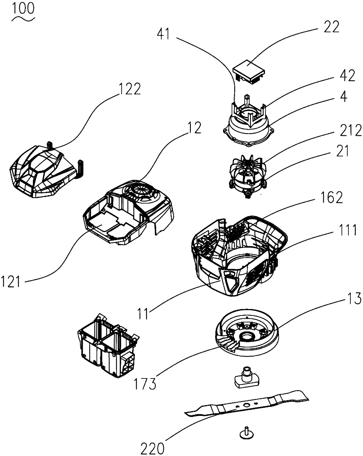
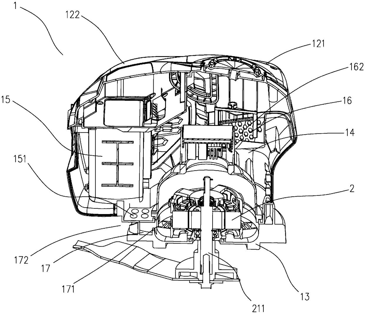
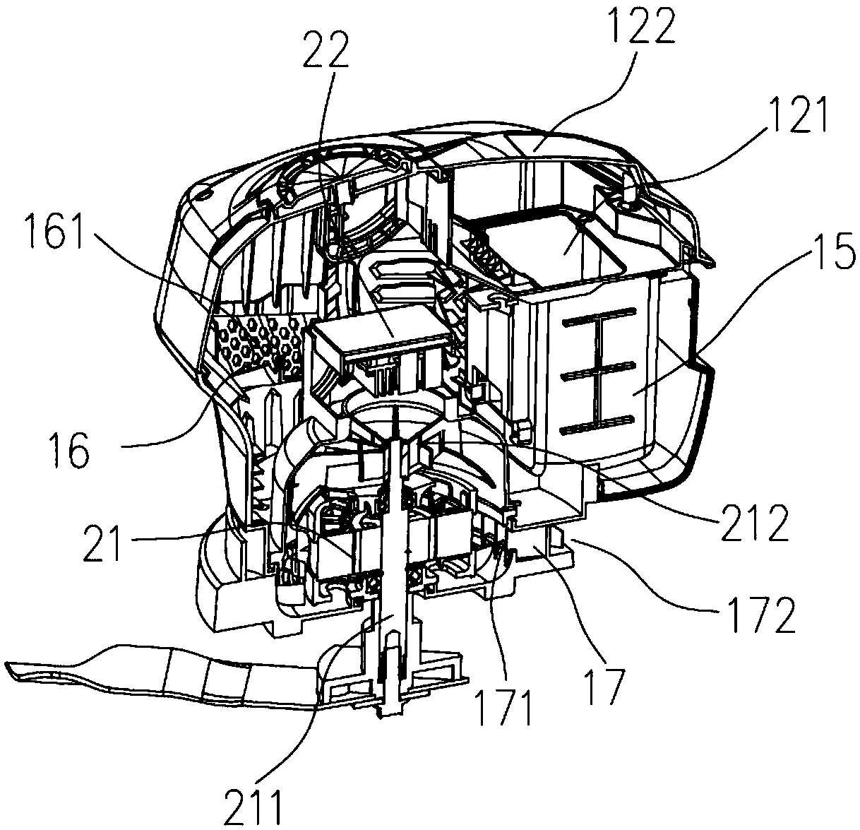
[0028] see figure 1 , figure 2 and Figure 7 Shown is the power assembly 100 provided by the present invention. The power assembly 100 includes a housing 1, a driving device 2 housed in the housing 1, a power supply device 3 and a wind deflector 4, the power supply device 3 is used to provide power for the driving device 2, so that the power assembly 100 is connected and installed on the garden tool 200 and drive the garden tool 200 to work. In this embodiment, there are two power supply devices 3 , and it can be understood that at least one power supply device 3 is protected by the present invention.

[0029] Please also refer to Figure 1 to Figure 8 As shown, the housing 1 includes a first housing 11 , a second housing 12 and a third hous...


PUM


Abstract

The invention provides a power assembly and a garden tool. The power assembly comprises a shell, a driving device, a power supply device and an air guide hood, and the driving device, the power supplydevice and the air guide hood are accommodated in the shell; the driving device comprises a driving motor provided with motor fan blades and a control panel assembly, and the air guide hood is connected to the shell to accommodate the driving motor; the shell is provided with an air inlet used for air inlet and an air outlet used for air outlet, and the air outlet is a side opening facing the shell. According to the power assembly, the air outlet is set to be the side opening facing the shell, and thus airflow entering the shell through the air inlet can flow through the control panel assembly and the driving motor in sequence, and finally flow out of the shell through the air outlet; the using power is high while it is guaranteed that the power assembly has an efficient cooling function;meanwhile, the garden tool applying the power assembly has good waterproof performance and using safety.

Description

technical field [0001] The invention relates to a power assembly and a garden tool, belonging to the field of garden tools. Background technique [0002] The heat dissipation of the power components in the existing garden tools is carried out by passive heat dissipation or active heat dissipation. For small garden tools such as lawn mowers, most of them use active heat dissipation. In the prior art, the lawn mower with active heat dissipation is to set the air outlet at the blade on the bottom surface of the bottom shell under the power assembly. In this way, on the one hand, the suction wind formed when the blade rotates can be used to dissipate heat; on the other hand, , can blow away the grass clippings and dust attached to the surface of the blade in time. [0003] However, in actual use, the juice produced by cutting grass blades will mix with dust and condense on the bottom shell and the blade, so the suction wind formed when the blade rotates alone cannot completely...

Claims


Application Information

Patent Timeline
Patent Type & Authority Applications(China)
IPC IPC(8): A01D34/68A01D34/82A01D75/18H02K9/00
CPCA01D34/68A01D34/828A01D75/18H02K9/00H02K9/06H02K5/14A01D34/64A01D34/78A01D34/81A01D2101/00
Inventor 冯守川陈文海
Owner CHANGZHOU GLOBE CO LTD
Learn More