High-pressure-resistant tee forming machine capable of improving yield

A high-pressure-resistant, forming machine technology, applied in the field of high-pressure-resistant three-way forming machines, can solve the problems of lower yield, insufficient water pressure of U-shaped pipes, water leakage, etc., and achieve the effect of increasing yield and avoiding internal water pressure loss

Inactive Publication Date: 2019-03-15
李世持
View PDF0 Cites 2 Cited by
  • Summary
  • Abstract
  • Description
  • Claims
  • Application Information

AI Technical Summary

Problems solved by technology

[0004] 1. During the process of injecting water into the U-shaped pipe, due to the high water pressure in the U-shaped pipe, it often causes the main piston rod to retreat. The retreat of the main piston rod will cause insufficient water pressure in the U-shaped pipe, and at the same time, the water in the U-shaped pipe will It will also leak out, which will affect the quality of the formation of the tee pipe when the subsequent main piston rod is advanced twice, resulting in waste products
[0005] 2. When the main piston rod is propelled for the second time, the material on the outer wall of the U-shaped pipe is rolled into the mold cavity of the main pipe of the three-way pipe, but due to the high water pressure inside the U-shaped pipe, the strong water pressure will cause the material to be pressed into the three-way pipe. The inner and outer walls of the mold cavity of the main pipe are broken by hydraulic pressure, which reduces the yield

Method used


Image

  • High-pressure-resistant tee forming machine capable of improving yield
  • High-pressure-resistant tee forming machine capable of improving yield
  • High-pressure-resistant tee forming machine capable of improving yield

Examples


Embodiment 1

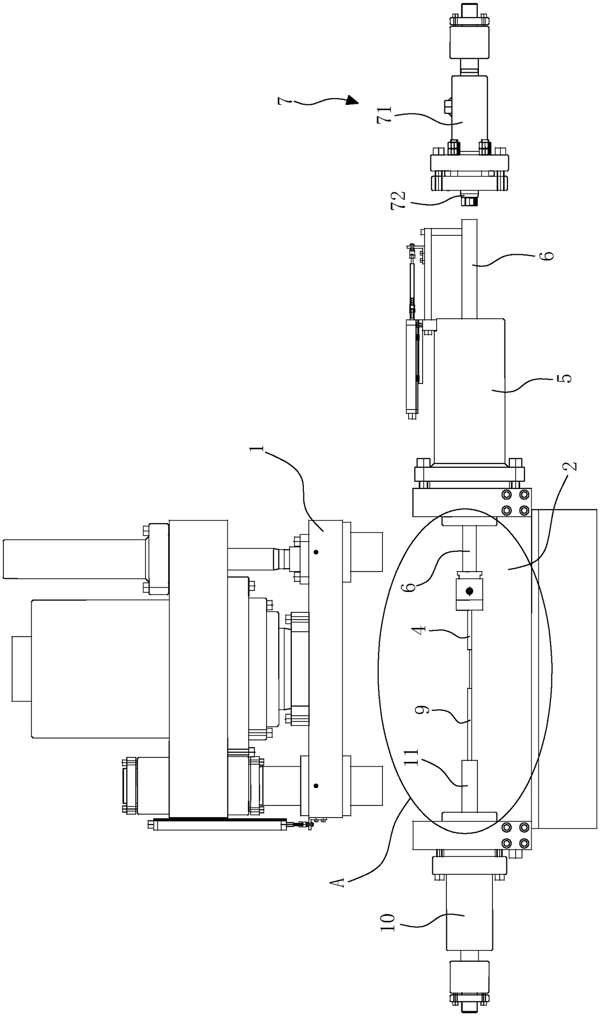
[0029] Embodiment 1. The telescopic anti-retraction device 7 stops the retreat oil cylinder 71. The retreat oil cylinder 71 is arranged at the tail of the main piston rod 6. The retreat stop piston rod 72 of the stop-retreat oil cylinder 71 is facing the tail end of the main piston rod 6 to prevent the main piston rod 6 from The backward movement is generated, which is achieved by the anti-retraction piston rod 72 against the end of the main piston rod 6. This structure will not affect the secondary forward movement of the main piston rod 6. After the production is completed, the anti-retraction piston rod 72 will retreat Reset, then the main piston rod 6 also retreats and resets.

Embodiment 2

[0030] Embodiment 2: The telescopic anti-retraction device 7 is a first electromagnetic telescopic device 73, and the first electromagnetic telescopic device 73 is installed above the tail end of the main piston rod 6. When the main piston rod 6 is pushed forward for the first time, the first electromagnetic telescopic device 73 starts, stretches out the electromagnetic piston rod 74, and blocks the end of the main piston rod 6 to prevent the main piston rod 6 from retreating. This structure will not affect the secondary forward action of the main piston rod 6. 74 is retracted and reset, and the main piston rod 6 is also retracted subsequently.

Embodiment 3

[0031] Embodiment three, telescopic anti-retraction device 7 is the second electromagnetic stretcher 75, the second electromagnetic stretcher 75 is arranged on the front end of the main piston rod 6, the first card 76 is installed on the main piston rod 6, and the second electromagnetic stretcher 75 is installed At the rear of the first card 76, when the main piston rod 6 is pushed forward for the first time, the second electromagnetic retractor 75 is activated, and the electromagnetic piston rod 77 is stretched out to block the rear end surface of the first card 76 to prevent the main piston rod from 6 retreats, after finishing production, electromagnetic piston rod 77 retracts, and then main piston rod 6 also retracts.


PUM


Abstract

The invention discloses a high-pressure-resistant tee forming machine capable of improving yield, which comprises an upper die and a lower die, wherein telescopic water injection guns are arranged inthe lower die corresponding to two branched pipe die cavities of a tee, the telescopic water injection guns are arranged at the front end of a main piston rod of a main oil cylinder, and a telescopicretreating stopping device is arranged beside the main piston rod. After the technical scheme is adopted, the high-pressure-resistant tee forming machine has the advantages that 1, before water injection is carried out, the main piston rod is firmly locked to prevent the situation that in the water injection process, the main piston rod retreats due to the fact that water pressure in a U-shaped pipe is sharply increased, so that loss of water pressure in the U-shaped pipe is avoided, and a condition is created for subsequent secondary forward pushing forming; and 2, by the cooperation of a forming auxiliary rod and the water pressure, in the calendering forming process, the outer wall of the U-shaped pipe is slowly calendered instead of being instantaneously finished, and the forming auxiliary rod retreats in the forming process and abuts against the outer wall of the U-shaped pipe, so that the outer wall is prevented from being crushed by strong water pressure due to over-excitation of forming, and the yield is improved.

Description

Technical field: [0001] The invention relates to a high-pressure-resistant tee forming machine capable of improving the yield. Background technique: [0002] At present, the relatively advanced production method of the tee pipe is made by hydraulic pressure calendering. The telescopic water injection gun at the front end of the main piston rod is inserted into the two nozzles of the U-shaped pipe, and water is injected into the U-shaped pipe. Push, at this time, the water pressure in the U-shaped pipe pushes the pipe wall at the junction of the three-way main pipe cavity and the U-shaped cavity to the direction of the three-way main pipe cavity, and finally obtains the required three-way pipe. [0003] There are two major problems in the production process of the above-mentioned molding process and equipment: [0004] 1. During the process of injecting water into the U-shaped pipe, due to the high water pressure in the U-shaped pipe, it often causes the main piston rod to ...

Claims


Application Information

Patent Timeline
Patent Type & Authority Applications(China)
IPC IPC(8): B21D26/037
CPCB21D26/037
Inventor 李世持
Owner 李世持
Why Eureka
Try Eureka