

In-cylinder grouting device used after self-balancing load box static load detection test and grouting method thereof
A technology of grouting device and static load detection, which is applied in the test of infrastructure, construction, infrastructure engineering, etc., can solve problems such as broken piles, and achieve the effects of grouting pressure monitoring, compact structure and convenient operation.
- Summary
- Abstract
- Description
- Claims
- Application Information
AI Technical Summary
Problems solved by technology
Method used
Image

Examples
Embodiment 1
[0032] Embodiment 1 is the grouting device in the cylinder after the static load detection test of the self-balancing load box, the following in conjunction with the attached figure 1 , 2 The present embodiment is described in detail:
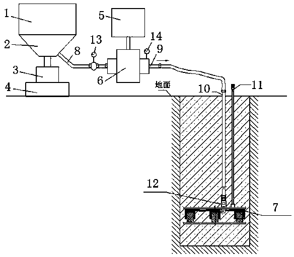
[0033] An in-cylinder grouting device after a static load detection test of a self-balancing load box, the device includes a stirring device 1, a filtering and stirring device 2, a stirring driving device 3, a weighing device 4, a boosting driving device 5, and a boosting grouting device 6 and cylinder grouting load box 7;
[0034] Below the stirring device 1 is a filter stirring device 2, the lower end of the filter stirring device 2 is connected to the stirring drive device 3, and the weighing device 4 is located below the stirring drive device 3;
[0035] The filtering and stirring device 2 is connected to the pressurized grouting device 6 through the suction port 8, and the pressurized grouting device 6 is connected to the pressurized dri...
Embodiment 2
[0043] Embodiment 2 is the grouting method of the grouting device in the cylinder after the static load detection test of the self-balancing load box, below in conjunction with the attached figure 1 , 2 The present embodiment is described in detail:
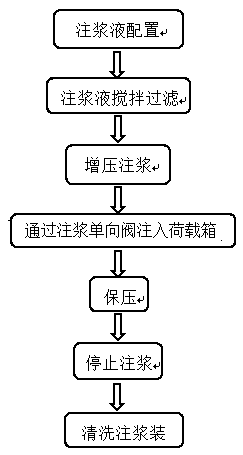
[0044] A grouting method for a grouting device in a cylinder after a static load detection test of a self-balancing load box, characterized in that the grouting liquid is weighed by the weighing device 4 and then enters the stirring device 1 for mixing and stirring evenly, and the stirring time is 15 to 30 minutes After the slurry is evenly stirred, it enters the pressurized grouting device 6 through the filter stirring device 2 to perform pressurized grouting;
[0045] The pressurized grouting device 6 grouts the in-cylinder grouting load box 7 through the output grouting pipeline, and the grout is directly injected into the in-cylinder grouting load box 7 through the grouting check valve 12, and then passed through the in-cyli...
PUM
 Abstract
Description
Claims
Application Information