
Insulated operating rod for charged operation

An insulating operating rod and live operation technology, applied in the direction of contact operating parts, etc., can solve the problems of corona discharge, prone to corona discharge, and inability to effectively remove corona discharge, and achieve flexible installation and disassembly, easy transportation and effect used

Active Publication Date: 2019-03-15
STATE GRID ZHEJIANG ELECTRIC POWER CO LTD JINHUA POWER SUPPLY CO +1
View PDF3 Cites 0 Cited by
  • Summary
  • Abstract
  • Description
  • Claims
  • Application Information

AI Technical Summary

Problems solved by technology

[0003] The invention solves the problem that corona discharge is easy to occur when the insulating operating rod is live, and the corona discharge cannot be effectively removed, and provides an insulating operating rod for live work, which can effectively solve the problem that corona easily occurs when the operating rod is live. The problem of discharge, and can adapt to different sizes of joint forms

Method used


Image

  • Insulated operating rod for charged operation
  • Insulated operating rod for charged operation
  • Insulated operating rod for charged operation

Examples


Embodiment 1

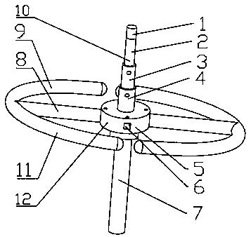
[0024] Such as figure 1 As shown, an insulating operating rod for live work includes a metal joint 1 , a telescopic part 10 , an insulating rod 7 , an installation and fixing part 12 and a protective part 11 .

[0025] Such as figure 1 As shown, the insulating rod 7 is a circular rod-shaped structure, and the insulating rod 7 is mainly used for holding. The metal joint 1 is used for live work, and the metal joint 1 can be set in different shapes according to the application occasion. In this embodiment, the metal joint 1 is cylindrical.

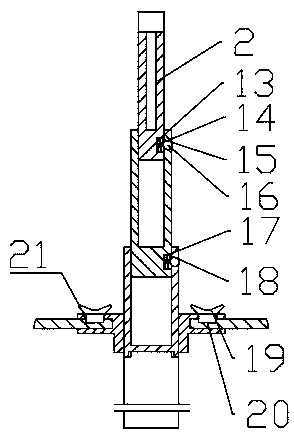
[0026] Such as figure 1 with figure 2 As shown, the telescopic part 10 includes a first telescopic rod 2 , a second telescopic rod 3 , a third telescopic rod 4 , a spring 16 and a steel ball 16 . One end of the telescopic part 10 is connected to the metal joint 1 , and the other end of the telescopic part 10 is connected to the insulating rod 7 . The first telescopic rod 2 is a cylindrical structure with one end closed and one end open,...

Embodiment 2

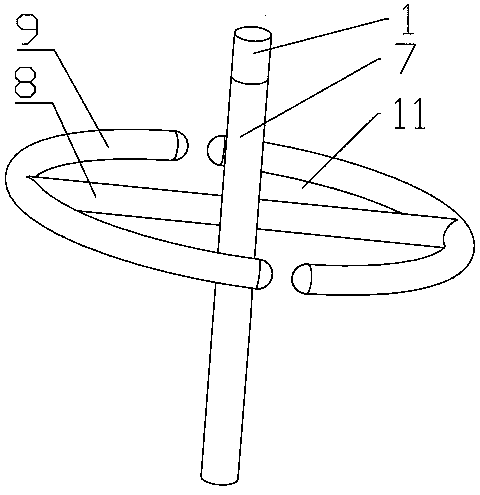
[0030] Such as image 3 As shown, an insulating operating rod for live work includes a metal joint 1, an insulating rod 7 and a protective part 11. The insulating rod 7 is a circular rod-shaped structure, and the insulating rod 7 is mainly used for hand-holding. The metal joint 1 is used for live work, and the metal joint 1 can be set in different shapes according to the application occasion. In this embodiment, the metal joint 1 is cylindrical. The protection part 11 includes a ring body 9 and a connecting rod 8, the ring body 9 is a circular ring structure with a circular cross section, and the connecting rod 8 is a rod-shaped structure with a circular cross section. The protection part 11 includes more than two ring bodies 9 , and in this embodiment the protection part 11 includes two ring bodies 9 . A gap is provided between the ring bodies 9 , and the gaps between the ring bodies 9 are equal. The gap between the ring bodies 9 is less than five times the ring width of th...


PUM


Abstract

The present invention relates to an insulated operating rod for charged operation. The insulated operating rod for charged operation comprises an insulating rod for hand-held, a metal joint connectedwith the insulating rod, and a protective portion electrically connected with the metal joint and capable of reducing corona discharge. According to the technical scheme of the present invention, problems that the corona discharge is easy to occur when the insulated operating rod is in charged operation, and the corona discharge cannot be effectively removed are solved; and by using the insulatedoperating rod for charged operation provided by the present invention, not only the problem that the corona discharge is easy to occur when the operating rod is in charged operation can be effectivelysolved, but also the insulated operating rod for charged operation can adapt to different sizes of joint forms.

Description

technical field [0001] The invention relates to the field of high-voltage electric equipment design, in particular to an insulating operating rod for live work. Background technique [0002] With the large-scale construction and development of my country's power grid, in order to meet the safety of power grid operation and power supply reliability, the demand and frequency of live work in my country have increased rapidly in recent years. Insulated operating tools are widely used in live work. For live work insulated operating rods or support booms, the operating head and joints must meet a certain mechanical strength, and metal joints are often used. When the metal joint of the insulating rod is located near the high-voltage charged body, the local electric field distribution will be uneven due to the tip effect, and corona or tip discharge will easily occur, which will affect the safety of workers and the performance of tools. And in the process of live work, because join...

Claims


Application Information

Patent Timeline
IPC IPC(8): H01H3/02
CPCH01H3/02
Inventor 方玉群崔建业孔晓峰王斌梁加凯金德军刘凯余光凯朱亦振邢哲鸣顾浩李进荣赵俊杰
Owner STATE GRID ZHEJIANG ELECTRIC POWER CO LTD JINHUA POWER SUPPLY CO
Learn More